Soken DAC-PD-7 - Partial Discharge Measuring Equipment.


DAC-PD-7 is an ideal PD tester for quantitative diagnosis at production and inspection of electrical parts, such as EV motor, Photo-coupler, IGBT, and insulation materials, etc. PD tests according to the international standard (IEC 60270, 60664-1. 61730-2) are available with PC Software.
Test Materials
- Solar Battery Panel Back Sheet.
- Photo-coupler
- IGBT
- EV Motor
- Lithium-Ion Battery
- Relay, Circuit Board
- High-Frequency Transformer
- Insulation Materials
Conformity
- IEC 60270: High-voltage test techniques – Partial discharge measurements
- IEC 60664-1: Insulation coordination for equipment within low-voltage systems – Part 1: Principles, requirements, and tests
- IEC 61730-2: Photovoltaic (PV) module safety qualification - Part 2: requirements for testing
What is Partial Discharge
Fig.1 is a general partial discharge occurrence model, and showing insulation sandwiched by electrodes. In the insulation, there are voids (impurities). The dielectric constant of the voids is usually lower than that in the surrounding dielectric. Therefore when AC voltage is applied to the insulation, the voltage in the voids becomes larger, and as a result, the voids short itself out, while the insulations are not shorted. The short circuit in the voids leads to small charge-transfers, and this is called partial discharge.
- Partial discharge occurs within voids (impurities) due to the lower insulating strength.
- The electric field tends to concentrate on the voids because the dielectric constant of voids is lower than that of the main insulations. As a result, local insulation breakdown in the voids occurs.
- The insulation strength of voids depends on the type of gas, gas pressure in the void and void dimension.
- Partial discharge precedes an insulator breakdown.
- Partial discharge is described by the maximum discharged charge (Q-max pC).

Why is Partial Discharge Test Important
Even with a stringent manufacturing process, it is not always possible to manufacture solid insulations without creating voids (impurities). Generally, the void in solid insulation is filled with a gas, and it has lower breakdown strength than the main material. In addition, the permittivity of the void is invariably lower than that of the main insulation, and the electric field tends to concentrate on the void. Thus, even under normal working stress, the voltage across the void may exceed the breakdown value and partial discharge occurs. When partial discharge begins and repeats, it can damage the materials and may lead to failure of the whole high voltage power equipment. To secure the safety of electrical appliances, the quality of insulations must be regarded as the most important matter. Partial discharge measurements are the desirable test to find insulation defects and early failures in insulation materials. Periodic diagnosis enhances the safety of electrical appliances and can help to find symptoms before becoming a failure.
PC Software
- PD tests according to the applicable international standard (IEC 60270, 60664-1. 61730-2) are available with attached PC Software.
- Measurement results are plotted continuously and PASS or FAIL judgment comes soon after the test completes.
- Measured data are saved in CSV format, and the archives are possible.
V-Q Measurement
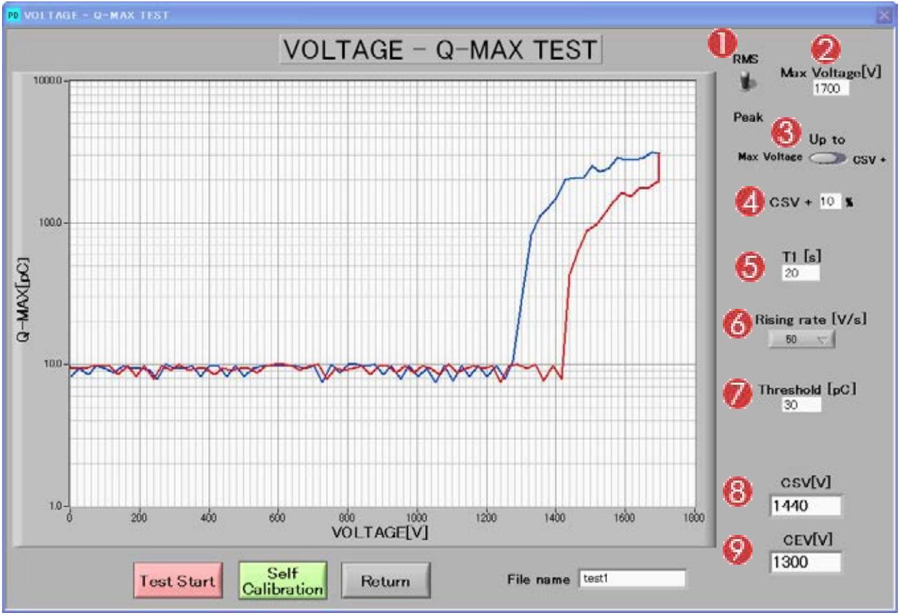
- Select “RMS” or “Peak”
- Max voltage to be applied.
- Select either “Max voltage” or “CSV”. When “Max voltage” is selected, the max voltage is applied to the specimen. When “CSV” is selected, the inception voltage plus ratio coefficient (%) will be applied. (ex. When inception voltage is 1000V and setting ratio is 10%, max test voltage will be determined as 1100V.)
- The ratio coefficient to be added to CSV. (0 – 20%)
- Max voltage duration time.
- Voltage rising-rate [V/s]
- Threshold value [pC]
- Inception voltage
- Extinction voltage
T-Q Measurement
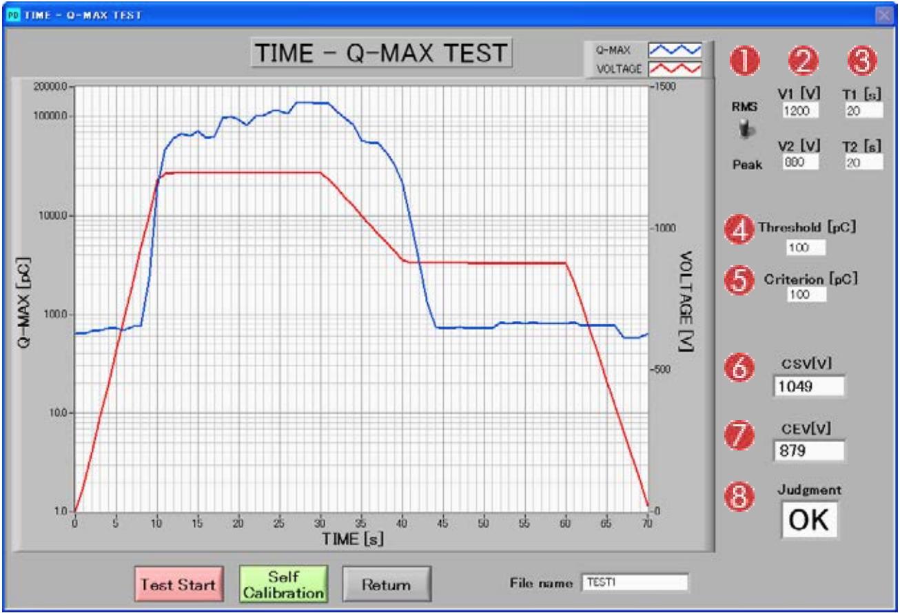
- Select “ RMS” or “Peak”
- Test voltage (V1 and V2)
- Hold time
T1: at voltage in V1
T2: at voltage in V2 - Threshold time [pC]
- Criterion [pC]
- Partial discharge extinction voltage
- Partial discharge inception (starting) voltage
- Judgment
Options
Partial discharge measurements are sometimes affected by a high background noise level if no appropriate measures are taken. Depending on the test environment and judgment PD level, a faraday room or a shielded box may be required. SOKEN can offer the tester with a shielded box upon request.
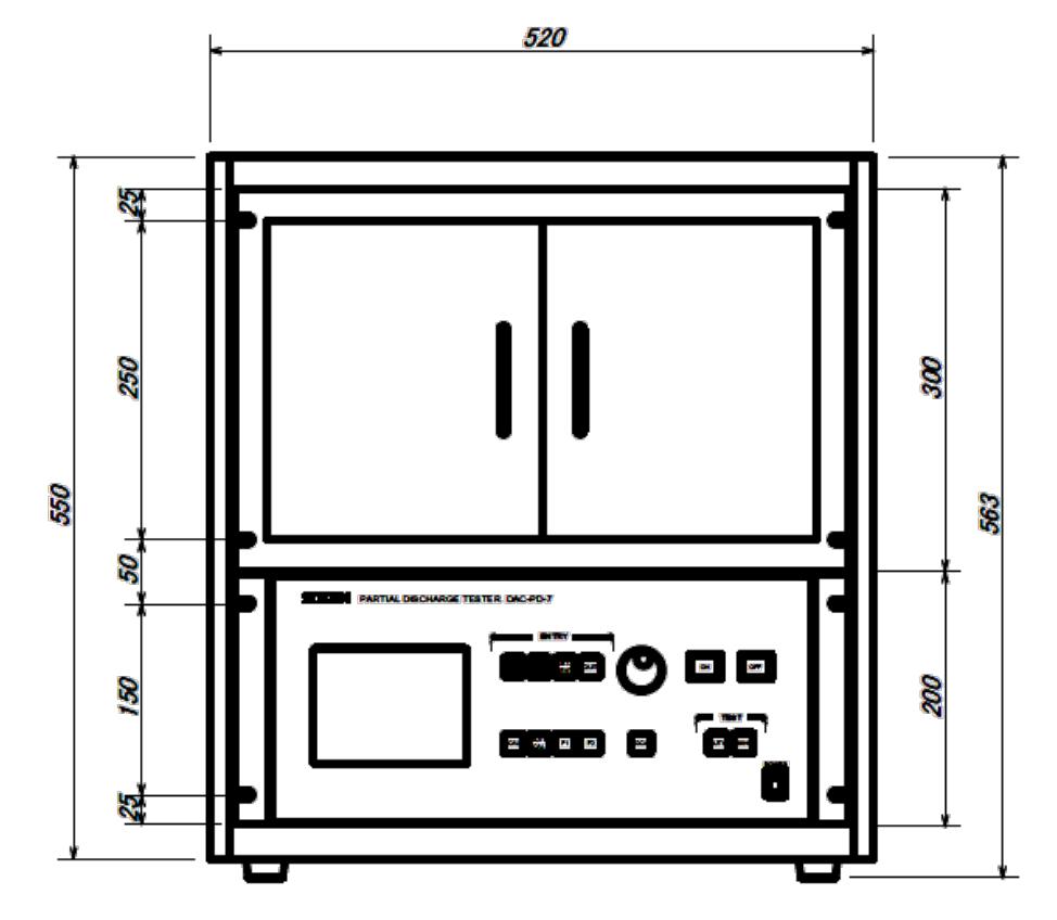
Example of Rack-in type:
Measuring cables are arranged inside of the system rack. Power cable, grounding cable, RS232C cable pulls out from a cable incoming hole on the bottom of the rack. Additional measures to start a partial discharge test will not be required.
Dimensions and designs are subject to be changed.
- All-IN-ONE UNIT: The tester contains a 3000V high voltage source, coupling capacitor, detector, and calibrator.
- EASY TO USE: No need cumbersome wirings.
- AUTOMATIC CALIBRATION FUNCTION: Depending on the calibration pulse level, the scale is adjusted and an adequate range is selected automatically.
- AUTOMATIC GAIN ADJUSTMENT: Automatic gain adjustment happens in designated intervals. No need to switch measurement ranges.
- LCD DISPLAY TO OBSERVE LIVE DISCHARGE WAVEFORM: Measurement can be conducted while observing discharge waveform. The applied voltage profile can be observed simultaneously.
- APPLICABLE TO IEC 60270, IEC 60664-1, IEC 61730-2: Software is included as a standard accessory
- RS232C INTERFACE: Automatic measurement with the attached software is possible.
- Measurement of the maximum discharge pulse Q-max is possible in each cycle.
General
| Input Voltage | AC100V/115V/220V/240V ±10%, 50/60Hz |
| Output Voltage | AC 0 - 3000V |
| Voltage Ramp Rate | 25V/s, 50V/s (10V/s, 25V/s, 50V/s and 100V/s with software) |
| PD Resolution | 0.01pC (Partial discharge in device <1pC at AC3000V) |
| Frequency | 50Hz, 60Hz |
| Waveform | Sine wave (not depend on waveform of Input Power) |
| Distortion of waveform | <3% |
| Fluctuation of Voltage | <1% |
| Maximum Load Current | 10mA |
| Maximum Capacitance Load | 5000pF |
| Voltage Accuracy | ±(1%+10digit) of readings |
| Voltage Setting Range | 0 – 3000V in 1V Steps |
| Gain | 0~80dB |
| Range | 1000pC, 10000pC, 100000pC |
| Response Occurrence Frequency | 10 - 9000PPS (Rate) |
| Calibrator Charge | 100pC, 1000pC |
| Calibration Pulse Injection Capacitor | 50pF |
| Calibration Pulse Voltage | 2V, 20V |
| Calibration Pulse Generation Frequency | 50PPS |
| Internal Coupling Capacitor | 1000pF |
| Interface | RS232C |
| Size | 430x380x200(WxDxH) Weight 15Kg |
| Software | Attached |
| Option | Shield Case, Electrode |
Do you have a Partial Discharge Measuring Equipment. that needs to be calibrated?
We offer standard traceable calibration and ISO 17025 accredited calibration services.
Get your Partial Discharge Measuring Equipment. calibrated today! Click Here!
There are currently no reviews for this product.