GW Instek AFG-3032 - 30MHz Dual channel Arbitrary Function Generator
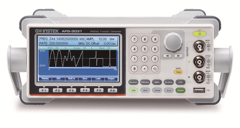

GW Instek rolls out the new AFG-3000 series arbitrary function generators, including 20MHz/30MHz single channel and dual channel models, designed to meet industry, scientific research, and education applications. In the design of isolated output, all output channels are earth ground isolation, which is suitable for test applications of floating circuit. For instance, connecting an AFG-3000 with a power supply’s DC voltage, the maximum AC-DC cascaded output reaches +42V or -42V. Each channel of dual channel models can be operated independently or multi units can simultaneously function without taking grounding reference into consideration. Applications are, for instance, the ignition control or transmission device of automotive electronics. The series features sample rate of 250MSa/s, 16-bit resolution, and 8M point memory depth for arbitrary waveform generation. Users not only can save the edited waveforms to the memory to build arbitrary waveforms, but also rebuild waveforms by the AFG-3000’s built-in DSOLink function with a GW Instek digital storage oscilloscope.
The AFG-3000 series supports synchronized phase for multi channel operation up to 6 units and 12 channels. A reference input connector is available allowing an external 10 MHz time base to synchronize the internal clock and elevate the frequency output accuracy. The series supports frequency sweep and amplitude sweep that can also integrate other functions, including linear/logarithm, one-way (saw tooth)/two-way (triangle), continuous/single trigger/gated trigger to meet various application requirements by applying different sweep methods. Frequency sweep tests the frequency response of electronic components such as filter and low frequency amplifier. Amplitude sweep simulates vibration tests (requires a vibration tester), and it also conducts aging tests of various materials and linearity tests of low frequency amplifier.
The main features of the AFG-3000 series include output amplitude from 1mVpp to 10Vpp (connected with a 50 ohm load); frequency range from 1uHz to 20MHz or 30MHz; 1uHz frequency resolution; and built-in sine, square, pulse, triangle, ramp, DC voltage, harmonic and noise. The waveform width, rise edge time and fall edge time of pulse waveform can be adjusted flexibly. Pulse waveform, with duty cycle from 0.017% to 99.983%, can be applied as trigger signals. Users can conduct arbitrary editing via 65 built-in function waveforms. The series supports AM/FM/PM/FSK/PWM modulation, frequency sweep, amplitude sweep and burst to satisfy industrial application requirements. Dual channel models provide SUM modulation, coupling, tracking, and phase to meet the test requirements of differential signal, phase control and amplifier distortion. Built-in 8th harmonic signal generator simulates harmonic signal of switching power supplies and it also tests EMI power filter characteristics. The AFG-3000 series provides free arbitrary waveform editing software (AWES) for users to quickly edit waveforms from the built-in diagrams so as to execute measurements.
The AFG-3000 series comes with four models. Model number and channel (s) are listed as follows:
| Model | AFG-3031 | AFG-3032 | AFG-3021 | AFG-3022 |
| Frequency Range | 1 uHz to 30MHz | 1 uHz to 30 MHz | 1 uHz to 20 MHz | 1 uHz to 20 MHz |
| Channel | 1 | 2 | 1 | 2 |
Circuit Design for Ground Isolation among Output/Input Terminal, Instrument Chassis, and Dual Channels
Channel 1, channel 2, reference 10 MHz input, synchronization and modulation input/output connector grounding are isolated from instrument chassis. The output channels of dual channel models are independently isolated. These connectors can sustain maximum isolation voltage up to ±42Vpk (DC+ AC peak value) to earth ground that is ideal for floating circuit tests. Multi units output can be executed without factoring in grounding reference issue. The built-in DC bias voltage of the AFG-3000 series can be applied on various waveforms. The DC bias voltage is ±5V under 50 ohm load. Automotive electronic applications such as ignition controller or transmission devices require higher DC bias voltage. As shown in the following diagrams, when the Voffset of the power supply is 32Vdc, the maximum output of the AFG is 20Vpp, and the maximum voltage output to the ground is 42V. If Voffset is 41Vdc, the maximum output of the AFG is 2Vpp and the maximum voltage output to the ground remains to be 42V. Therefore, an external power supply can be used to bring up the DC bias voltage to ±42Vpk (DC+ AC peak value).

Connection diagram for AFG connecting with power supply to increase D.C. bias.

The Vout of AFG is 20/2 Vpp when DC bias is 32/41 Vdc.

Test settings: power supply output -31.8V, and AFG-3032 output 20Vpp, 1kHzz sine wave.

The test result obtained from an oscilloscope (high impedance load). The lowest voltage was -42.4V.
Multi Channel Synchronized Phase Operation
Users can implement multi channel synchronized-phase operation up to 6 units and 12 channels (AFG-3032/3022). There are two methods to execute synchronized phase applications. Under different multiple frequency settings, master unit can synchronize the phase of each channel of the slave units. At 10 MHz reference frequency input (REF IN) connector, users can input 10 MHz atomic clock frequency standard via external signal source to increase frequency output accuracy.

Method one uses reference frequency output (REF OUT) and reference frequency input (REF IN), 50 ohm BNC cable (RG-58A/U) and T type BNC connector to connect up to 6 units to conduct synchronized phase operation.

Method two uses reference frequency output (REF OUT) and reference frequency input (REF IN) ), 50 ohm BNC cable (RG-58A/U) to connect up to 4 units to conduct synchronized phase operation.
Harmonic Signal Generator
Harmonic signal generator simulates the harmonic signal of switching power supplies and conducts characteristics tests on EMI power filter. Users can set order number and phase for harmonic signals to obtain desired signals. The following diagrams show 8th harmonic signal.

Harmonic Signal Generator

Harmonic Signal
Pulse Generator
The output frequency for pulse reaches 25 MHz and its duty cycle is from 0.017% to 99.983%. Users can set pulse width, duty cycle, rise edge time, fall edge time and edge time to support trigger signal. The following diagrams show settings for pulse signal.

Pulse Generator

Pulse
Versatile Output Waveform Selections

Sine

Square

Triangle

Ramp

Pulse

Noise

Harmonic

DC Voltage
Modulation Function
The series supports AM, FM, PM, FSK, PWM and SUM modulation. Modulation source can be from inside or outside. Applications include the baseband of communications systems, motor control and light adjustment.

Amplitude Modulation

Frequency Modulation

Phase Modulation

Frequency-Shift Keying Modulation

Pulse Width Modulation

SUM Modulation
Burst Function
The series supports N-period or gated trigger. Phase angle, duration time, frequency, waveform infinite can be adjusted to meet non-continuous output applications.

Burst Setting

Burst Signal
Sweep Function
The series supports frequency sweep and amplitude sweep that can also integrate other functions, including linear/logarithm, one-way (saw tooth)/two-way (triangle) waveforms, continuous/single trigger/gated trigger to meet various application requirements by different sweep methods. Frequency sweep carries out tests on the frequency response of electronic components such as filter and low frequency amplifier. Amplitude sweep simulates vibration tests (requires a vibration tester), and it also conducts aging tests of various materials and linearity tests of low frequency amplifier.

Amplitude Sweep Setting

Amplitude Sweep Signal

Frequency Sweep Setting

Frequency Sweep Signal
Flexible Arbitrary Waveform Editing
Four methods to obtain arbitrary waveforms.
Front Panel Operation

Via single unit’s panel, arbitrary waveforms can be selected, edited, stored, recalled, output, triggered from 65 built-in waveforms.
CSV File Upload

Support CSV file upload produced by MATLAB and Excel.
Direct Waveform Reconstruction

Collocate with GDS series digital oscilloscopes to retrieve waveforms and upload them to arbitrary generator to achieve direct waveform reconstruction.
Arbitrary Waveform Editing PC Software

Use AWES to edit complex waveforms. The software supports waveform mathematical operation. The waveform series includes Uniform Noise, Gaussian Noise, Rayleigh Noise, various digital codes such as non zero code, Manchester and RS-232, etc.
Correlated Functions of Dual Channel Outputs
AFG-3032/3022 models support independent channel or correlated channel applications. Four correlated functions are provided including SUM modulation, coupling, tracking, and phase.
- SUM modulation combines two signals and outputs the signal via one single channel. Combining noise and sine waveform to execute speaker’s distortion test is one of the applications.
- Coupling function arbitrarily sets ratio and difference for frequency and amplitude between two channels to realize a simultaneous effect for all parameters of dual channel. The example is amplifier using third order interpolation point (IP3) measurement to simulate signal output of two different frequency oscillators.
- Tracking function produces differential signal with same frequency, same amplitude, and 180 degree phase difference.
- Phase function arbitrarily sets phase parameters between two channels such as simulating sine/ cosine/square signal phase adjustment.
- 1uHz to 20 or 30MHz, 16-bit resolution with 1 mVpp to 10 Vpp amplitude. 1 or 2 channel (s)
- 250 MSa/s sampling rate for higher time resolution arbitrary waveforms
- 8M Points/channel standard waveform memory
- Input/output signal ground independent of housing and signal ground between channels also insulated.
- Synchronized phase operates up to 6 units and 12 channels
- Pulse waveform parameters can be set independently for more precise timing
- Harmonic signal generator
- Dual channel models support SUM modulation, coupling, tracking, and phase functions
- Built-in AM/FM/PM/FSK/PWM/SUM modulation, sweep and burst functions
- Provide USB/LAN/GPIB (optional) instrument control interface
Features
| Channels | 2 |
| I/O signal ground for the instrument chassis | Isolation |
| Connector shells for channel output(s), Sync output, 10MHz REF Input, Mod Input and Mod output are isolated from the instrument’s chassis. Maximum allowable voltage on isolated connector shells is ±42 Vpk. (DC + AC Peak) | |
| Each of the signal ground of CH1 & CH2 | Isolated |
Arbitrary Waveforms
| Sample Rate | 250 MSa/s |
| Repetition Rate | 125MHz |
| Waveform Length | 8M points |
| Amplitude Resolution | 16 bits |
| Non-Volatile Memory | Ten 8M waveforms (1) |
| User define Output Section | Any section from2to 8M points |
| Trigger | External |
| Built-in Arbitrary Waveforms | Sine, Square, Ramp, Sinc,Pulse, DC, Sin(x)/x, Exponential Rise, Exponential Fall, Negative Ramp, Absatan, Havercosine, Sinever, Abssin, Haversine, Stair_down, Abssinehalf, N_pulse, Stair_UD, Ampalt, Negramp, Stair_up, Attalt, Rectpuls1, Stepresp, Diric_even, Roundhalf, Trapezia, Diric_odd, Sawtoot, Tripuls1, Gauspuls1, Sinetra, Dlorentz, ln, Sqrt, Exporise, Lorentz, Xsquare, Expofall, Gauss, Since, Arccos, Arctan, Sech, Arccot, Arctanh, Sinh, Arccsc, Cosh, Tan, Arcsec, Cot, Tanh, Arcsin, Csc, Arcsinh, Sec, Barthannwin, Chebwin, Kaiser, Bartlett, Flattopwin, Triang, Blackman, Hamming, Tukeywin, Bohmanwin, Hann |
Frequency Characteristics
| Sine / Square | 1uHz to 30MHz |
| Pulse | 1uHz to 25MHz |
| Triangle / Ramp | 1uHz |
| Resolution | 16 bits |
| Accuracy Stability | ±1 ppm 0 to 50°C ±0.3 ppm 18 to 28°C |
| Accuracy Aging | ±1 ppm, per 1 year |
| Accuracy Tolerance | ≦ 1 uHz |
Output Characteristics (2)
| Amplitude Range | 1 mVpp to 10 Vpp (into 50Ω) 2 mVpp to 20 Vpp (into open-circuit) |
| Amplitude Accuracy | ± 1% of setting ±1 mVpp (at 1 kHz / into 50Ω without DC offset) |
| Amplitude Resolution | 0.1 mV or 4 digits |
| Amplitude Flatness | 0.1dB <10 MHz 0.2 dB 10 MHz to 30 MHz (sinewave relative to 1 kHz/into 50Ω) |
| Amplitude Units | Vpp, Vrms, dBm |
| Offset Range | ±5 Vpk ac +dc (into 50Ω) ±10Vpk ac +dc (into open circuit) |
| Offset Accuracy | 1% of setting + 2 mV+ 0.5% of amplitude |
| Waveform Output Impedance | 50Ω typical (fixed) > 10MΩ (output disabled) |
| Waveform Output Protection | Short-circuit protected Overload relay automatically disables main output |
| SYNC Output Level | - |
| SYNC Output Impedance | 50Ω nominal |
Sine Wave Characteristics
| Harmonic Distortion(5) | –60 dBc DC~1 MHz, Ampl<3 Vpp –55 dBc DC~1 MHz, Ampl>3 Vpp –45 dBc 1MHz~5 MHz, Ampl>3 Vpp –30 dBc 5MHz~30 MHz, Ampl>3 Vpp |
| Total Harmonic Distortion | < 0.2%+0.1mVrms DC to 20 kHz |
| Spurious (non-harmonic)(5) | –60 dBc DC~1 MHz –50 dBc 1MHz~20MHz –50 dBc+ 6 dBc/octave 1MHz~30MHz (AFG-3031/3032) |
| Phase Noise | <-110dBc/Hz typical,15 kHz offset, fc = 10MHz |
Square Wave Characteristics
| Rise/Fall Time | <8 ns (3) |
| Overshoot | < 5% |
| Asymmetry | 1% of period+1 ns |
| Variable Duty Cycle | 20.0% to 80.0%,≦ 25 MHz 40.0% to 60.0%,25 to 30MHz |
| Jitter | 0.01%+525ps < 2 MHz 0.1%+75ps > 2 MHz |
Ramp Characteristics
| Linearity | < 0.1% of peak output |
| Variable Symmetry | 0% to 100% (0.1% resolution) |
Pulse Characteristics
| Pulse Width | 20ns to 999,830s Period ≧ Width-0.625 [(Rise Time-0.6ns)+(Fall Time-0.6ns)] |
| Duty setting range | 0.017% to 99.983% |
| Period | 40ns to 1,000,000s |
| Rise Time and Fall Time | 9.32 ns to 799,900s (0.01ns or 3 digit resolution) |
| Resolution | 0.0001% |
| Overshoot | <5% |
| Jitter | 50ps typical (<10kHz) |
Harmonic
| Harmonic order | ≦8 |
| Harmonic Type | Even, Odd, All, User Amplitude and Phase can be set for all harmonics |
AM
| Carrier Waveforms | Sine, Square, Triangle, Ramp, Pulse, Arb |
| Modulating Waveforms | Sine, Square, Triangle, Up/Dn Ramp |
| Modulating Frequency | 2 mHz to 20 kHz |
| Depth | 0% to 120.0% |
| Source | Internal / External |
FM
| Carrier Waveforms | Sine, Square, Triangle, Ramp |
| Modulating Waveforms | Sine, Square, Triangle, Up/Dn Ramp |
| Modulating Frequency | 2 mHz to 20 kHz |
| Peak Deviation | DC to 30 MHz (1uHz resolution) |
| Source | Internal / External |
PM
| Carrier Waveforms | Sine, Triangle, Ramp |
| Modulating Waveforms | Sine, Square, Triangle, Up/Dn Ramp |
| Phase Deviation | 0° to 360°, 0.1° resolution |
| Modulating Frequency | 2 mHz to 20 kHz |
| Source | Internal |
PWM
| Carrier Waveforms | Square |
| Modulating Waveforms | Sine, Square, Triangle, Up/Dn Ramp |
| Deviation | 0% ~ 100.0% of pulse width, 0.1% resolution |
| Modulating Frequency | 2 mHz to 20 kHz |
| Source | Internal / External |
Additive Modulation (Sum)
| Carrier Waveforms | Sine, Triangle, Ramp, Pulse, Noise |
| Modulating Waveforms | Sine, Square, Triangle, Up/Dn Ramp |
| Ratio | 0% to 100% of carrier amplitude, 0.01% resolution |
| Modulating Frequency | 2 mHz to 20 kHz |
| Source | Internal / External |
FSK
| Carrier Waveforms | Sine, Square, Triangle, Ramp |
| Modulating Waveforms | 50% duty cycle square |
| Internal Rate | 2 mHz to 1 MHz |
| Frequency Range | DC to 30MHz |
| Source | Internal / External |
Sweep
| Waveforms | Frequency Sweep: Sine, Square, Triangle, Ramp Amplitude Sweep: Sine, Square, Triangle, Ramp, Pulse, Noise, ARB |
| Type | Frequency, Amplitude |
| Functions | Linear or Logarithmic |
| Direction | Up or Down |
| Start F / Stop FREQ | Any frequency within the waveform's range |
| Sweep Time | 1 ms to 500 s (1 ms resolution) |
| Trigger Mode | Single, External, Internal |
| Trigger Source | Internal / External |
Burst
| Waveforms | Sine, Square, Triangle, Ramp, Pulse, Noise |
| Frequency | 1uHz to 30MHz (4) |
| Burst Count | 1 to 1,000,000 cycles or Infinite |
| Start / Stop Phase | -360.0∘to +360.0∘ (0.1° resolution) |
| Internal Period | 1 us to 500 s |
| Gate Source | External Trigger (pulse waveforms can only be used in gate mode) |
| Trigger Source | Single, External or Internal Rate |
| Trigger Delay | N-Cycle, Infinite: 0us to 100s (1us resolution) |
External Modulation Input
| Type | AM, FM, PWM, Sum |
| Voltage Range | ± 5V full scale |
| Input Impedance | 10kΩ |
| Frequency | DC to 20 kHz |
| Modulation Output | AFG-3031/3021 only |
| Type | AM, FM, PM, PWM, SUM, Sweep |
| Amplitude Range | ≧ 1Vpp |
| Impedance | > 10kΩ typical |
External Trigger Input
| Type | For FSK, Burst, Sweep, N Cycle ARB |
| Input Level | TTL Compatibility |
| Slope | Rising or Falling (Selectable) |
| Pulse Width | > 100 ns |
| Input rate | DC to 1 MHz |
| Input Impedance | 10kΩ,DC coupled |
| Latency Sweep | < 10 us (typical) |
| Latency Burst | < 100 ns (typical) |
| Jitter Burst | 2.5 us |
| Jitter Burst | 1 ns; except pulse,300 ps |
10MHz Reference Output
| Output voltage | 1 Vp-p / 50 Ω square wave |
| Output Impedance | 50 Ω, AC coupled |
| Output Frequency | 10MHz |
10MHz Reference Input
| Input Voltage | 0.5Vpp to 5Vpp |
| Input Impedance | 1k Ω, unbalanced, AC coupled |
| Input Frequency | 10MHz ± 10Hz |
| Waveform | Sine or Square (50±5% duty) |
| Ground Isolation | 42Vpk max. |
External-Sync
| Phase Delay (max.) | Series Connection: 39+(N-2)*39 ±25nS Parallel connection: (N-1)*6 ±25nS (where N=number of connected units) |
| Maximum number of connected units | Series Connection: 4 Parallel Connection: 6 |
| Applicable Functions | Sine, Square, Triangle, Pulse, Ramp, Harmonic, MOD, Sweep, Burst |
| Store/Recall | 10 Groups of Setting Memories |
| Interface | GPIB(Optional), LAN, USB |
| Display | 4.3 inch TFT LCD, 480 × 3 (RGB) × 272 |
General Specifications
| Power Source | AC 100~240V , 50~60Hz |
| Power Consumption | 85VA |
| Operating Environment |
|
| Operating Altitude | 2000 meters |
| Pollution Degree | IEC 61010 Degree 2, Indoor Use |
| Storage Temperature | -10 ~ 70∘C, Humidity: ≤70% |
| Dimensions (WxHxD) | Bench Top : 265 (W) x 107 (H) x 374 (D) |
| Weight | Approx. 4kg |
| Safety Designed to | EN61010-1 |
| EMC Tested to | IEC-61326, EN 55011 |
| Accessories | Test cable(GTL-110×1 for AFG-3031/AFG-3021, GTL-110×2 for AFG-3032/AFG-3022), User Manual Compact Disk × 1, Quick Start Guide × 1, Power cord × 1 |
(1). A total of ten waveforms can be stored. (Every waveform can composed of 8M points maximum.)
(2). Add 1/10th of output amplitude and offset specification per ∘C for operation outside of 0∘C to 28∘C range (1-year specification).
(3). Edge time decreased at higher frequency.
(4). Sine and square waveforms above 25 MHz are allowed only with an "Infinite" count.
(5). Harmonic distortion and Spurious noise at low amplitudes is limited by a -70 dBm floor.
Do you have a 30MHz Dual channel Arbitrary Function Generator that needs to be calibrated?
We offer standard traceable calibration and ISO 17025 accredited calibration services.
Get your 30MHz Dual channel Arbitrary Function Generator calibrated today! Click Here!
There are currently no reviews for this product.