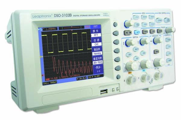
Leaptronix DSO-3102BS - 100MHz Digital Storage Oscilloscope with 40MHz Arbitrary Function Waveform Generator

DSO-3000 series digital storage oscilloscopes provide you with excellent performance and strong functions in a compact design. Even as a new generation of portable low-priced general product, the series still offers many measurement functions of middle or high end product and meets your measurement requirement with affordable cost.
With bandwidth 60MHz , 100MHz and 200MHz, the series offers a maximum real-time sampling rate of 1Gsps and equivalent sampling rate of 50Gsps to ensure you accurate observation of signal details. Many standard configured advanced characteristics such as multi trigger modes, auto measurement, digital filtering, waveform storage, math function, FFT, PASS/FAIL judgement, multi communication interfaces, etc. make the measuring more convenient and quickly.
Application Fields
- Laboratory and training center in colleges and universities
- Production line test and quality Control
- Test and measurement in R&D department
- Maintenance and after-sales service
Prominent Signal Measuring Capability
Observation of the signal more clearly
DSO-3000 Series has a 5.6-inch 320x234 TFT LCD color display for watching signals from any viewing angle. Different from traditional oscilloscope’s fixed menu display, DSO-3000 series can display the waveform to full screen according to your need.
Single MENU ON/OFF key enables you to view more information in 25% more display area.
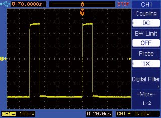
Figure 1 Normal display with menu on
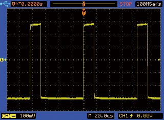
Figure 2 Full-screen display with menu off
Deep memory depth for capturing more
Maximum 2.4Mpts memory depth for each channel on all models, DSO-3000 series is easy to record and analyze the waveform. Even under the slow time base settings, you can maintain a high sampling rate. This allows you observe the signal in more details. In a given sampling rate, the more sampling points mean the longer the time observed.
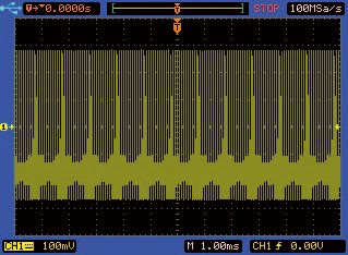
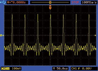
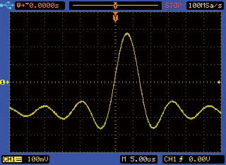
Figure 3 Deep memory depth waveform display
Delayed sweep mode for both details and the whole waveform
In Delayed sweep mode, you can view simultaneously the details on a particular part and the whole waveform. Through split display you can zoom in on a particular area on your signal while still viewing the entire captured waveform.
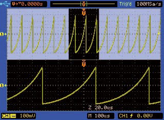
Figure 4 Delay mode to observe signal details
Powerful Functions
DSO-3000 series oscilloscope is your indispensable assistant to get your job done easier and faster.
Auto scale
Auto scale can evaluate all input signals and set the correct condition to best display the signals. Single period or multi periods can be selected to display in the current display window.
Running control
RUN/STOP mode:
To continuously observe waveform or freeze the current waveform on the screen.
SINGLE mode:
To automatically recognize signal meeting trigger conditions,and to immediately sample the signal to fixedly display,especially suitable to sample single signal.
Math Function and FFT
DSO-3000 series provides some important math operations, including addition, subtraction, multiplication, or 1024-point FFT (Fast Fourier Transforms). For time-domain signal analysis, you can use additions (signal superimpose), subtraction (elimination of noisy component or differential operation, etc.), multiplication (frequency mixing, etc.) processes.
For frequency-domain analysis, you have FFT (Fast Fourier Transforms) with five window function (Rectangular, Hanning, Hamming, Blackman, Flat-Top). And spectrum amplitudes of FFT can be displayed in linear or dBV (RMS) scale type.
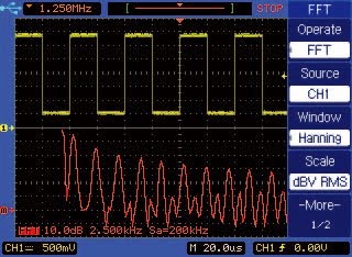
Figure 5 FFT analysis (dBV)
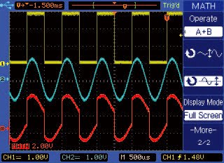
Figure 6 Addition operation
24 Automatic Parametric Measurements
DSO-3000 series provides up to 24 automatic parametric measurements. You can either install three commonly used screen measurements or display all the 24 measurements of the current selected source on the screen. Auto measurement can not only save your time for eye observation, but also provide you more accurate results. Without complicated operation, you can get your measurement results easily and quickly.
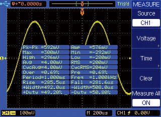
Figure 7 Auto measurement display
Convenient observation of all signals
Roll mode:
It is one of the useful features of DSO-3000 series to test low-speed signal accurately. Using the Roll mode, the change of ultra slow speed signal can be observed.
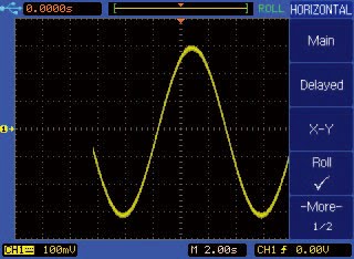
Figure 8 Slow speed signal in Roll mode
X-Y mode:
In X-Y mode, channel 1 becomes the X input and channel 2 becomes the Y input. Lissajou’s figure can be displayed to calculate phase difference of same-frequency signals.
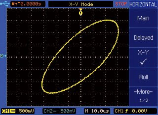
Figure 9 Lissajou’s figure in X-Y mode
Video Trigger:
DSO-3000 series can synchronously trigger on specified line or field of the standard NTSC or PAL/SECAM video signal.
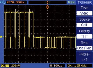
Figure 10 Video trigger mode for TV signal
More Functions
Digital Filter
DSO-3000 series provides several digital filters, including low pass, high pass, band pass, and band reject filters. It can be applied to displayed signals to acquire expected results, such as to simulate the effect of a hardware filter, to reject aliasing noise or error signal to clearly observe a signal of interest, etc. The high and low cut-off frequency can be set randomly.
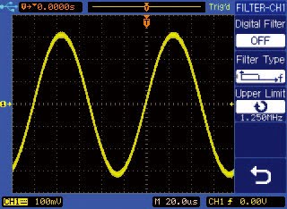
Figure 11 Signal with noises
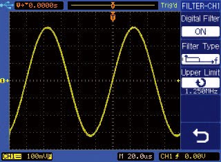
Figure 12 Signal processed with a low pass filter
Waveform Record and Replay
DSO-3000 series can record the input signal over a period of time continuously in the internal or external memory for future analysis. Up to 1000 frames can be recorded with the variable time interval ranging from 1 ms to 1000s. The recorded frames can be played back continuously or played frame by frame, so that you can observe any frame and capture any tiny abnormality.
PASS/FAIL Judgment
On the production line, it is valuable to judge some kind of signal and decide if it is good or not. DSO-3000 series can measure the selected input signal and compare it with the predefined PASS/FAIL regulations and then output the PASS/FAIL result. This function is more convenient and quick and reduces error os man-made judgement.
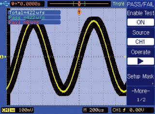
Figure 13 PASS/FAIL measurement
Auto Calibration
DSO-3000 can automatically calibrate its vertical, horizontal and trigger system, so that it can work with the best measurement accuracy.
Unique Built-in Function/Arbitrary Waveform Generator Module
- The first digital oscilloscope with built-in function/ arbitrary waveform generator module in the world
- More accurate, stable and low distortion output with the help of advanced DDS technology
- 200MSa/S sampling rate, 14bits vertical A/D resolution
- 10MHz / 20MHz / 40MHz sine/ square waveform frequency output
- Maximum 10MHz impulse signal frequency output
- Up to 30 kinds of built-in waveforms , such as sine, square, triangular wave etc.
- Built-in multiple modulation function, including AM, FM, PWM, FSK, PSK and Bias modulation.
- 1uHz ~ 10MHz/1uHz ~ 20MHz/1uHz ~ 40MHz frequency sweep in Up, Down and Round sweep mode.
- Up to 30 kinds of commonly used waveforms burst output, including sine, square, triangular waveforms
- 8kpts arbitrary waveform memory depth
- Realize the seamless connection between oscilloscope and function/arbitrary waveform generator
Flexible Human-Machine Interface
Logical and easy operation
Different function areas, including input channels, time base, trigger channel and function areas, are positioned and marked respectively, so that it is easy to access and operate. The main front-panel keys light when the corresponding funct ions are available or active. This human-oriented feature makes your job much easier.
Figure 14 The front panel key board
Multi interface selections
The instrument provides multi interfaces, including USB host interface used to store waveform files (BMP, CSV file format) to an USB disk by simply pressing “PRINT” key, and USB device interface or RS232 interface used to communicate with a computer to control the instrument or to transmit the waveform data.
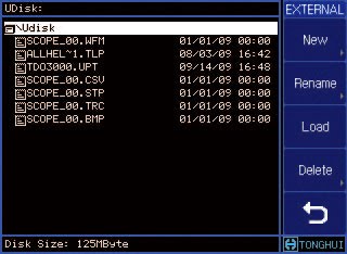
Figure 15 USB disk file system
Software update
The latest updated software of DSO-3000 series can be downloaded free from our website, and can be loaded to the corresponding oscilloscope through the USB host interface.
- Signal bandwidth: 60MHz/100MHz/200MHz
- Real-time sampling rate: Max. 1Gsps Equivalent
- Sampling rate: Max. 50Gsps
- 5.6-inch TFT LCD Color display with better clearance, multi-color schemes available.
- With up to 2.4Mpts memory depth, more signal details can be seen.
- Independent vertical scale and position control knobs for each channel.
- Edge, Pulse width and Video trigger mode available. Alternating triggering function is also available to stably display asynchronous signals.
- Unique variable trigger sensitivity to suit special measurement requirements on different occasions.
- Math functions including add, subtract, multiply and 1024-point FFT.
- Up to 24 kinds of parameters automatic measurements.
- Advanced cursor modes: Manual, Auto and Track
- Practical low-pass, high-pass, band-pass, band-reject digital filters with adjustable cut-off frequency.
- Unique waveform recording and playback function.
- PASS / FAIL detection, optical isolated PASS/FAIL output.
- Built-in 5 digits hardware frequency counter.
- Auto-calibration feature.
- Multiple language user interface.
- Pop-up menu, the user operation more convenient and intuitive.
- Embedded help information system in Chinese and English.
- Up to 10 internal setup and waveform files memories, external storage of setup, track, waveform, BMP bitmap and CSV files.
- USB Host Port, Support USB disk storage, and firmware upgrade can be carried out through an USB disk.
- PRINT button pressed to directly store the screen image (BMP) or the waveform data (CSV) in an USB disk.
- USB device, LAN (only for B series) and RS232C interface for the instrument remote control
- Upgrade the working procedure via USB HOST.
Sampling System
| Max real time sampling rate | Series B:1Gsps |
| Max equivalent sampling rate | Series B:50Gsps |
| Memory depth | Single channel ON:2.4Mpts Double channel ON:1.2Mpts |
| Vertical A/D resolution | 8 Bits |
| Sampling mode | Sample, Peck detect, Averaging |
| Auto scale | Automatically set vertical scale(V/div), time base(s/div), and trigger mode. |
Vertical System
| Channels | 2 analog input channels and 1 trigger input channel |
| Bandwidth | 100MHz |
| Coupling | DC, AC and GND |
| Bandwidth limit (-3dB) | 20MHz |
| Calculated rise time | <3.50ns |
| Vertical scale (V/div) | Series B: 2mV/div to10V/div 1-2-5 step |
| Vertical gain accuracy | 2mV/div, 5mV/div ±4% × reading ±0.1div × V/div+0.5mV; 10mV/div to 10V/div ±3% × reading±0.1div × V/div+1mV; |
| Vertical offset range | ±8 div away from the screen center |
| Probe attenuation factor | ×1, ×10, ×100, ×1000 |
| Input impedance | 1MΩ||18pF |
| Delay differential | ±150ps when vertical scale and coupling settings are identical |
| Max. input voltage | 400V (DC+AC peak,@1MΩ) |
| Probe compensation output | 3Vp-p, 1kHz |
Horizontal System
| Time base range (1-2-5step) | 2ns—50s/div |
| Horizontal mode | Main, Delayed, X-Y and Roll |
| Time base accuracy | ±0.01% |
| XY mode (Input) | X-axis input (horizontal): CH1 Y-axis input (vertical): CH2 |
| XY mode (Bandwidth) | 100MHz |
| XY mode (Phase error) | ±3° |
Trigger System
| Trigger source | CH1, CH2, EXT, EXT/5, LINE, Alternating |
| Trigger mode | Auto, Normal, Single |
| Trigger coupling | DC, AC, LF-reject, HF- reject |
| Trigger type | Edge, Pulse width, Video |
| Trigger level range | Internal: ±8 div from screen center; EXT:±1.6V; EXT/5: ± 8V |
| Trigger sensitivity | 0.1div to 1.0div user adjustable |
| EXT input impedance | 1MΩ||18pF |
| EXT max. Input voltage | 400V (DC+AC peak,@1MΩ) |
Signal Measurement
| Voltage parameters | Max, Min, VPP, High, Low, Amplitude, Average, RMS, Overshoot, Preshoot, Cycle average, Cycle RMS |
| Time parameters | Frequency, Period, Rise time, Fall time, +Width, -Width, +Duty, -Duty, Delay, Phase, X@MAX, X@MIN |
| Math functions | A-B, A+B, A×B, FFT(1024points) |
| Cursor measurement | Manual, Auto, Track |
| Hardware frequency counter | 5-digit frequency counter up to full bandwidth |
Storage & Interface
| Internal storage | 10 setup files and 10 trace files |
| File format | Setup, Waveform, Trace, BMP and CSV file |
| Interface | USB HOST, USB DEVICE, RS232C and PASS/FAIL OUT,LAN |
Display System
| Display screen | TFT LCD display, 5.6-inch |
| Resolution | 320( horizontal )×234(vertical) dot matrix |
| Color | 24 bit true color |
| Menu language | Simplified Chinese, Traditional Chinese, English etc. |
| Waveform Display (Scale) | Menu ON : 8div(vertical) × 10div(horizontal) i.e. 200(vertical) × 250(horizontal) dot matrix Menu OFF : 8div(vertical) × 12div(horizontal) i.e. 200(vertical) × 300(horizontal) dot matrix |
| Waveform Display (Type) | Dot , Vector |
| Waveform Display (Interpolation) | (Sinx)/x, Linear |
| Waveform Display (Persistence) | Off, Infinite |
| Waveform Display (Format) | YT / XT |
Other Specifications
| Operation ambient temperature & humidity | 0°C to 40°C, ≤90%RH |
| Line voltage | 99V to 242V AC,47Hz to 440Hz |
| Power consumption | ≤ 50VA |
| Instrument dimension | 320mm(W) × 156.5mm(H) × 123mm(D) |
| Net weight | Approx. 2.5kg |
Arbitrary Function Waveform Generator Specifications
Frequency Characteristics
| Sine, Square waveform | 1μHz--40MHz |
| Pulse waveform | 1μHz--10MHz |
| Other waveforms | 1mHz--1MHz |
| Frequency resolution | 1μHz(Sine, Square, Pulse), 1mHz(other) |
| Frequency accuracy | ≤±5×10⁻⁴ |
| Frequency stability | ±5×10⁻⁵ |
Sine Characteristics
| Harmonic Distortion | <5MHz: -50dBc/td> |
| ≤10MHz: -45dBc | |
| >10MHz: -40dBc | |
| Total harmonic distortion | 20Hz--100kHz: ≤0.2% |
Amplitude Characteristics
| Amplitude range into open circuit | When freq.≤ 20MHz, 2mVpp to 20 Vpp When freq. > 20MHz, 2mVpp to 6 Vpp |
| Max resolution into 50Ω | 1μVp-p |
| Max resolution into open circuit | 2μVp-p |
| Amplitude accuracy | ≤±2%+1mV (1kHz sine waveform) |
| Frequency accuracy | ≤±5×10⁻⁴ |
| Amplitude stability | ±1 % in 4 hours |
| Amplitude flatness (Sine, Square, Pulse) |
When freq. ≤ 5 MHz: ±5% When freq. > 5MHz: ±10% |
| Amplitude flatness (other waveforms) |
When freq. ≤ 50 kHz: ±5% When freq. > 50kHz: ±20% |
| Output impedance | 50Ω |
AM Modulation Characteristics
| Carrier waveforms | Sine, Square |
| Source waveforms | 30 commonly used waveforms, including Sine, Square, Triangle etc. |
| Source frequency | 1mHz to1MHz |
| Source depth | 0% to 120% |
FM Modulation Characteristics
| Carrier waveforms | Sine, Square |
| Source waveforms | 30 commonly used waveforms, including Sine, Square, Triangle etc. |
| Source frequency | 1mHz to1MHz |
| Frequency deviation | 1% to 99.9% |
PWM Modulation Characteristics
| Carrier waveforms | Pulse |
| Source waveforms | 30 commonly used waveforms, including Sine, Square, Triangle etc. |
| Source frequency | 1mHz to1MHz |
| Width deviation | 1% ~ 99% |
FSK Modulation Characteristics
| Carrier waveforms | Sine |
| Hop frequency | 1μHz to 40MHz |
| Interval time | 1ms to 40s |
PSK Modulation Characteristics
| Carrier waveforms | Sine |
| Hop Phase | 0° to 360° |
| Interval time | 1ms to 40s |
DCOM Modulation Characteristics
| Carrier waveforms | Sine, Square |
| Source waveforms | 30 commonly used waveforms, including Sine, Square, Triangle etc. |
| Source frequency | 1mHz to1MHz |
| Function description | Realize addition of carrier waveform and modulated waveform |
Frequency Sweep Characteristics
| Waveforms | Sine, Square |
| Frequency range (≤ 6 Vpp) | 1μHz to 40MHz |
| Frequency range (> 6 Vpp) | 1μHz to 20MHz |
| Sweep mode | Up, Down, Round |
| Sweep time | 1ms to 500s |
Burst Characteristics
| Waveforms | 30 commonly used waveforms, including Sine, Square, Triangle etc. |
| Counts | 1 to 60000 cycles |
| Burst frequency | 1mHz to1MHz |
Do you have a 100MHz Digital Storage Oscilloscope with 40MHz Arbitrary Function Waveform Generator that needs to be calibrated?
We offer standard traceable calibration and ISO 17025 accredited calibration services.
Get your 100MHz Digital Storage Oscilloscope with 40MHz Arbitrary Function Waveform Generator calibrated today! Click Here!
There are currently no reviews for this product.