Graphtec America GL980 - Midi Logger


High Speed 1 MS/S Simultaneous Sampling With Isolated Input
GL980 is equipped with an isolated input mechanism to protect signals from interferrences caused by noise from other channels. 16-bit A/D converter adopted to achieve hi-speed and hi-resolution measurements.
Multifunction Input
Voltage, temperature, humidity, logic and pulse measurements can all be taken simultaneously in high speed.
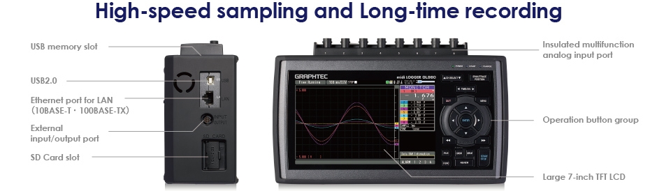
Large Easy-To-Read 7 inch LCD
Adopts large TFT LCD with multiple methods for displaying information.
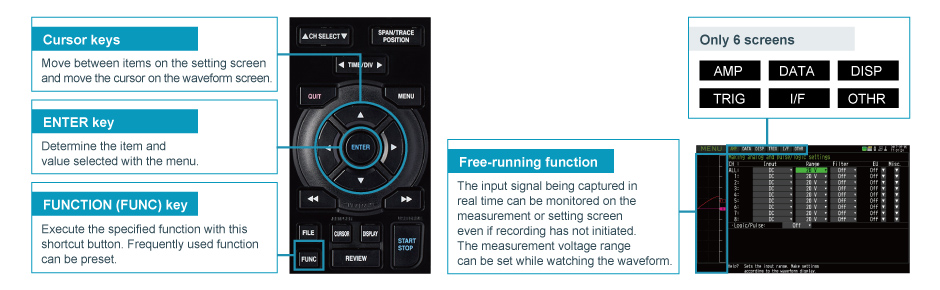
Quick and Easy Set Up Process
Simple operation with cursor and enter keys with six pre-set menu screens on large LCD.
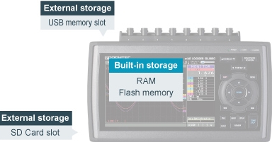
Supports Large Built-in RAM (4MS/CH) and Built-in Flash (4 GB)
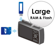
Long term recording is made possible with 4 M sampling/ch built-in RAM and 4 GB built-in Flash memory. It supports both USB Flash memory and SD Card memory to be used as external storage devices for recorded data for certain sampling intervals.
Typical Applications
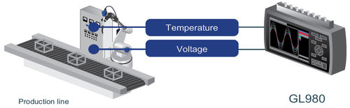
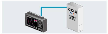
Measurement of Control Device
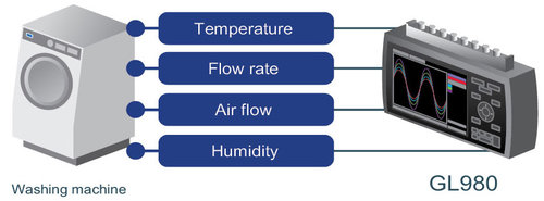
Measurement for Testing Washer and Dryer
Measurement as an XY Recorder
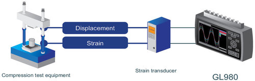
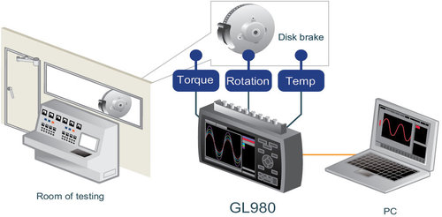
Measurement for Brake Component Testing
High Speed 1MS/s Simultaneous Sampling with Isolated Input
GL980 is equipped with an isolated input mechanism to protect signals from interferences caused by noise from other channels. 16-bit A/D converter adopted to achieve hi-speed and hi-resolution measurements.
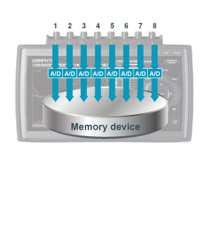
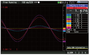
Simultaneous Sampling
GL980 utilizes simultaneous sampling to eliminate slowdown in sampling rate by using multiple A/D converters in simultaneous sampling method. Eight individual A/D converters in each channel sustains the maximum sampling speed for all eight channels to measure high speed rapid voltage fluctuation and multi-channel vibration measurement.
Sampling interval: 1 µs to 1 min (in steps of 1, 2, 5)
External Sampling Function
Sampling of the logger is performed in sync with an external device using an external signal input.
Maximum input frequency: 100 kHz
* B-513 Input/Output cable for GL is required.
Multifunction Input
Measure Repetitive Wave Forms Such as Vibration with Instantaneous Value and Effective Value
Measures either instantaneous value or effective value (RMS). By utilizing the trigger feature to measure abnormal spikes in the continuous waveform, users can measure vibration abnormalities repeatedly.
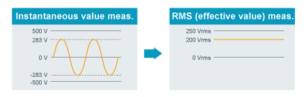
Measures Abnormalities in a Repeated Waveform by Effectively Measuring the Corresponding RMS Value
All RMS measurement range with Crest Factor: up to 2
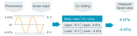
Scaling (Engineering Unit) Function
Measured voltage value can be converted to a specified engineering unit. The value can be displayed with the physical measurement value of the sensor and be saved into the data file with the converted values.
Calculation Function Between Channels
our arithmetic operations (Addition, subtraction, multiplication and division) are available using two analog input channels.
* Data can be saved only in GBD file format.
Example
CH2 = CH3 * CH1
(CH2 is a value obtained by multiplying the values of CH3 and CH1)
* Value of calculated results are displayed and saved into data file.
Trigger Function
The trigger in this unit has multiple functions including level trigger of input signal value for each channel.
Trigger action
Start or stop capturing data by triggering
Trigger source
Off, Measured signal level, Alarm, External, Scheduled time, Scheduled day, Elapsed time
* When trigger is used for starting action, level of measured signal can be set for each channel.
Threshold
Analog input: High or Rising, Low or Falling, Window-in, Window-out
Logic input: H or L (4-channel signal pattern)
Pulse input: High or Rising, Low or Falling, Window-in, Window-out
Combination: Level OR, Level AND, Edge OR, Edge AND
Alarm Function & Signal Output
Threshold of an alarm can be set for each channel. When an alarm is triggerred notification is sent by following methods.
Alarm threshold
Analog input: High, Low, Window-in, Window-out
Logic input: H or L (signal in each channel)
Pulse input: High or Rising, Low or Falling, Window-in, Window-out
When alarm is detected
- Display to screen (Digital value of alarm's origin channel is displayed in red)
- Save alarm information to measurement data file
- Output alarm signal :
- Number of channel: 4 channels (Output channel can be arranged to each source channel in OR condition.)
- Signal type: Open collector (pull-up to 5 V with 10 kΩ resistor), maximum load is the 24 V and 100 mA.
* Requires Input/Output cable for GL series (B-513 Option).
Large Easy-to-Read 7 inch LCD
Monitor data in multiple methods in addition to digital value display and full waveform display screen.
Y-T Waveform Monitor Screen
Displays data with analog waveform and digital value. Screen can also be split into 1, 2, 4 or 8 zones to display the channels in different zones.
Digital Monitor Screen
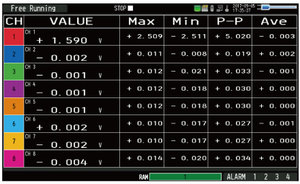
Displays current data in digital value and results of real time statistical calculation. (Function: Maximum, Minimum, Peak-to-peak, and Average) When displays only current data, it can be shown in 1, 2, 4 or 8 zones.
Past Waveform Monitor Screen
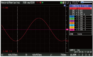
Display the past part of the data while capturing data. Execute without stopping measurement and also scroll past data. Data screen can be switched with past and current.
XY Graph Monitor Screen
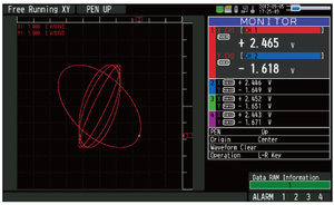
Emulates the classic XY chart recorder. Also supports features for pen up/down and position movement.
Quick and Easy Set Up Process
Other Helpful Functions
Delivers reliable measurements at a location with unstable power supply.
Equipped with three types of options for power source, AC adapter, DC input, and battery pack. With a battery pack, GL980 runs continuously for approximately 2 hours. If an AC power fails, it will automatically switch from the AC adapter to the battery pack. Additionally, when the voltage of the battery pack reaches low, measurement is automatically stopped after saving the data file preserving the accumulated data. (Requires two battery packs (B-569 option) installed.)
Instrument is in Compliance with JIS Vibration Test for Automobile Type 1 Class A
(Vibration durability test: 5 m/s2)
Accessories
-
Carrying case (B-581) [comming soon]
Portable case to store GL980 and signal input cable for easy handling. -
Cover
Protect the main body from cosmetic damages and minor impacts. GL980 is shipped with cover attached.
* The cover is not to protect from hard impact.
Supports Large Built-in RAM (4MS/CH) and Built-in Flash (4GB)
Approximate recording time
• 8 channels of analog input. • Data is saved as a GBD file.
Long term recording is made possible with 4 M samples/ch built-in RAM and 4 GB built-in Flash memory. It supports both USB Flash memory and SD Card memory to be used as external storage devices for recorded data for certain sampling intervals.
| Memory type | Data capacity |
1MS/s (1μs) |
100kS/s (10μs) |
1kS/s (1ms) |
1S/s (1s) |
|---|---|---|---|---|---|
| Built-in RAM | 4 M samples/ch | 4 seconds | 40 seconds | 66 minutes | 46 days |
| Built-in Flash memory | 3.9 GB | N/A | N/A | 2 days 6 hrs. | Over 1 year |
| External memory (SD/USB Flash memory)* | 4 GB | N/A | N/A | 2 days 11 hrs. | Over 1 year |
■ 8 channels of analog input with 4 channels of Pulse input. ■ Data is saved as a GBD file.
| Memory type | Data capacity |
1MS/s (1μs) |
100kS/s (10μs) |
1kS/s (1ms) |
1S/s (1s) |
|---|---|---|---|---|---|
| Built-in RAM | 4 M samples/ch | 4 seconds | 40 seconds | 66 minutes | 46 days |
| Built-in Flash memory | 3.9 GB | N/A | N/A | 1 days 4 hrs. | Over 1 year |
| External memory (SD/USB Flash memory)* | 4 GB | N/A | N/A | 1 days 7 hrs. | Over 1 year |
* When using 8 GB or larger memory, the size of data file will be up to 4 GB. The Relay mode enables extended recording time.
Convenient Data Recording Functions
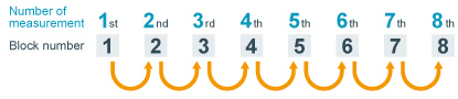
Memory Division Function

Built-in RAM can be divided into 1, 2, 4, or 8 blocks with multiple high-speed recording measurement using the trigger function.
SINGLE BLOCK
When multiple measurements are executed, the captured data is overwritten in memory block 1.

DIVIDED INTO 8-BLOCKS
When multiple measurements are executed, recorded data is stored in the next memory block.
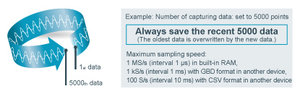
Ring Mode

Saves most recent data of specified number after recording stops.
Number of capturing data 1000 to 10000000 data
* When using built-in RAM, 10 to 4000000 data
Auto Save Function
Recorded data saved in a built-in RAM is automatically copied as data file to a built-in Flash memory, SD Flash memory card or USB Flash memory with auto save function. An SD Flash memory card or a USB Flash memory can be used as a backup location when using the built-in RAM. The process will prevent losing any data captured in the built-in RAM by any overwrite or power cycles.
Data Backup and Hot Swaps

The recorded data can automatically save to other storage device at specified regular intervals during data capture. (Maximum sampling speed: 1 kS/s (interval 1 ms) with GBD format, 100 S/s (interval 10 ms) with CSV format)
When the backup destination is set to a SD Flash memory card or a USB Flash memory device, memory device can be exchanged before the memory capacity becomes full using the key operation.
Search Function
The search function can locate a specific value within the captured data as well as finding abnormal values within data of a long-recorded file.
Search content
Search for analog signal levels, logic signal pattern, pulse signal levels or alarm point in captured data.
- Analog signal channel: Signal levels in each channel
・Search mode: raising, falling, window-in, window-out - Logic signal channel: Signal level (H or L) in each channel
- Pulse signal channel: Signal levels in each channel
・Search mode: raising, falling, window-in, window-out - Alarm: Alarm detected point on selected alarm signal output channel
Main Unit Specifications
Display (LCD)
| Size | 7-inch TFT color LCD (WVGA: 800 x 480 dots) |
| Information | Waveform in Y-T with digital values, Enlarged waveforms, Digital values and Real-time statistical result values, XY graph |
| Language | English, French, German, Spanish, Russian, Chinese, Korean, Japanese |
Interface to PC
| Type | Ethernet (10 BASE-T/100 BASE-TX), USB2.0 |
| Function | Data transfer to PC (up to 1 ms sampling), Control command to GL980 |
| Ethernet functions | Web server function, FTP server function, NTP client function, DHCP client function, Email send function |
| USB function | USB mode (File transfer and deletion from built-in flash and SD on GL980) |
Trigger function
| Trigger action | Start or stop capturing data by triggering |
| Trigger source | • Start: Off, Measured signal, Alarm, External, Scheduled time, Scheduled day, Elapsed time • Stop: Off, Measured signal, Alarm, External, Scheduled time, Scheduled day, Elapsed time |
| Combination | Level OR, Level AND, Edge OR, Edge AND |
| Threshold | • Analog (*1): High or Low in level mode, Rising or Falling in edge mode, Window-in, Window-out • Logic: H or L (4-channel signal pattern) • Pulse: High or Rising, Low or Falling, Window-in, Window-out |
| Repeat action | Off, On (Re-armed automatically) |
| Trigger hold out | Hold off repeat action in specified period • Mode: Previous start to next start, previous stop to next start • Time: zero second (no hold off) to 9999 hrs. 59 min. 59 sec |
| Defection accuracy | ± 0.5 % of measurement range |
| Pre-trigger | Up to the number of capturing data points (max. 4000000) specified in built-in RAM (only when built-in RAM is used) |
Alarm function
| Alarm action | Displays and outputs a signal when alarm is detected |
| Threshold | • Analog input: High, Low, Window-in, Window-out • Logic input: H or L (signal in each channel) • Pulse input: High or Rising, Low or Falling, Window-in, Window-out |
| Combination | OR (Source channel can be assigned with OR condition to output port) |
| Detection cycle | Link with analog sampling |
| Alarm holding | On or Off |
| Detection accuracy | ± 0.5 % of measurement range |
Storagve device
| Built-in RAM | Four million samples for each channel • Memory partition: 4 M samples x 1 bank, 2 M sample x 2 banks, 1 M samples x 4 banks, 500 k samples x 8 banks • Capturing data points: Specified 10 to 4000000 • Data type: Captured data • Auto-save: Transfer captured data to other devices after capturing is completed (It can be enabled or disabled) |
| Built-in Flash | 4 GB (for capacity of data: approx. 3.9 GB) • Data type: Captured data, Condition settings, Screen copy |
| External USB (*2) | Support USB Flash memory device (*3) by USB2.0 Type A port, Single port, No memory capacity limit • Data type: Captured data, Condition settings, Screen copy |
| External SD CARD (*2) |
Support SDHC memory card (up to 32 GB) by SD Card slot, Single slot • Data type: Captured data, Condition settings, Screen copy |
Capturing mode
| Mode | Off (Normal), Ring, Relay |
| Off (Normal) | Save data between start to stop |
| Ring (*4) | Save most recent data of specified number • Destination: Built-in RAM, Built-in Flash, USB or SD • Number of capturing data: 1000 to 10000000 data (*5) • Sampling: up to 1 MS/s (interval 1 μs) in built-in RAM, up to 1 kS/s (interval 1 ms) with GBD format in other device, up to 100 S/s (interval 10 ms) with CSV format in other device |
| Relay | Save data to multiple files with specified capturing time or file size (up to 4 GB) until recording data is stopped • Destination: Built-in Flash, USB or SD • Sampling: up to 1 kS/s (interval 1 ms) with GBD format, up to 100 S/s (interval 10 ms) with CSV format |
Data backup
| Interval | Off, 1, 2, 6, 12, 24 hrs., specific time, or any time with key operation • Sampling: up to 1 kS/s (interval 1 ms) with GBD format, up to 100 S/s (interval 10 ms) with CSV format |
| File destination | Built-in Flash, USB or SD |
| Hot-swapping external memory |
Hot-swapping USB or SD Flash memory with key operation during data backup |
Search function
| Function | Search for specific point in captured data |
| Search factor | • Analog: Signal levels in each channel • Logic: 4-channel signal pattern • Pulse: Rising, Falling, Window-in, Window-out in each channel • Alarm: Alarm triggering point |
Calculation function
| Statistical | Real-time: Display digital and statistical values at the same time • Function: Maximum, Minimum, Peak-to-peak (P-P), Average |
| Replay: Statistical values between cursors in replay captured data • Function: Maximum, Minimum, Peak-to-peak (P-P), Average, RMS |
|
| Between channels | Addition, subtraction, multiplication and division for two analog inputs (only in GBD format) |
Scaling (Engineering unit) function
| Measured value can be converted to the specified engineering unit • Analog voltage: Converts using four reference points (gain, offset) • Temperature: Converts using two reference points (offset) • Pulse count: Converts using two reference points (gain) |
Annotation function
| Comment can be set in each channel, up to 31 alphanumeric characters and symbols (Display first 8 characters on screen) |
Operating environment
| 0 to 40 ºC when driven by AC adapter or battery, 5 to 85 % RH (non condensed) |
Power source
| AC adapter: 100 to 240 V AC, 50/60 Hz DC power: 8.5 to 24 V DC (required cable option B-514) Battery pack: Two battery packs (option B-569) required |
Power consumption
| AC adapter (in 240 V AC) |
Approx. 48 VA (66 VA while charging battery) with disabling screen saver off Approx. 43 VA (62 VA while charging battery) with enabling screen saver on |
| DC drive (24 V) | Approx. 0.6 A (0.9 A while charging battery) with disable screen saver off Approx. 0.53 A (0.82 A while charging battery) with enabling screen saver on |
| DC drive (12 V) | Approx. 1.22 A (Cannot charge battery) with disable screen saver off Approx. 1.07 A (Cannot charge battery) with enabling screen saver on |
| DC drive (8.5 V) | Approx. 1.81 A (Cannot charge battery) with disable screen saver off Approx. 1.55 A (Cannot charge battery) with enabling screen saver on |
External dimensions [W×H×D]
| Approx. 260 x 161 x 83 mm (with the cover) |
Weight
| Approx. 1.7 kg (the cover is attached, AC adapter and battery are not included) |
Vibration resistance
| Compatible with JIS Vibration test method for automobile Type 1 Class A (Vibration durability test: 5 m/s²) |
(*1) It can set for each channel.
(*2) File size of captured data is up to 4GB in each file.
(*3) Standard USB memory devices are required.
(*4) Required minimum capturing time is 15 seconds in GDB format, 30 seconds with CSV format.
(*5) When using built-in RAM, 10 to 4000000 data
Analog Input Specifications
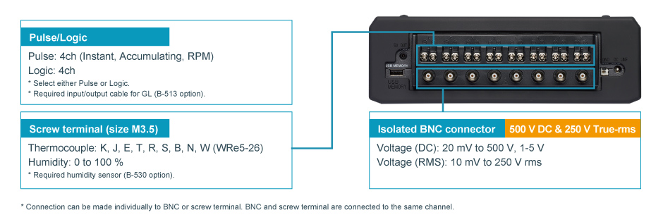
| Number of input channels | 8 channels |
| Type of input terminal | Isolated BNC connector and Screw terminal (M3.5 screw) (*6) |
| Input method | All channels isolated unbalanced input, Simultaneous sampling |
| Sampling speed (interval) | 1 M Samples/s to 1 Sample/min (1 μs to 1 min) and External (*7) • Sampling interval: 1, 2, 5, 10, 20, 50, 100, 200, 500 μs, 1, 2, 5, 10, 20, 50, 100, 200, 500 ms, 1, 2, 5, 10, 20, 30 sec, 1 min * When using built-in RAM: 1 μs to 1 min, using other storage: 1 ms to 1 min |
| Frequency response | DC to 200 kHz (within +1/-4 dB) |
| Filter (Low pass) | Off, Line (1.5 Hz), 5, 50, 500 Hz, 5, 50 kHz (at -3dB, -6dB/oct) |
| A/D converter | 16-bit (effective resolution: 1/40000 of the measuring full range) |
| R.J. Compensation | Internal or External |
| Burnout | Detecting burnout of Thermocouple with menu operation in free-run mode |
| Input impedance | 1 MΩ ±5% |
| Signal source impedance | up to 1 kΩ |
| Isolation resistance | Min. 50 MΩ (at 500 V DC) with between input and GND |
| Common-mode rejection ratio | Min. 90 dB (50/60 Hz, signal source impedance: max. 300 Ω) |
| Signal-noise ratio (S/N) | 20 mV range: - 40 dB (when input terminals + and - are shorted) Other range: - 50 dB (when input terminals + and - are shorted) |
Measurement Range
| Voltage (DC) | 20, 50, 100, 200, 500 mV, 1, 2, 5, 10, 20, 50, 100, 200, 500 V, and 1-5V F.S. |
| DC-RMS (DC coupling and rms value meas.) |
10, 25, 50, 100, 250, 500 mV rms, 1, 2.5, 5, 10, 25, 50, 100, 250 V rms F.S. • Crest Factor: up to 2 • Frequency response: 20 Hz to 10 kHz • Measures the accumulated value of the DC and AC components in effective value, that is a true-RMS |
| Temperature | Thermocouple: K, J, E, T, R, S, B, N, W (WRe5-26) |
| Humidity | 0 to 100 % RH - using the humidity sensor (option B-530) |
Measurement accuracy
| Voltage (DC) | ± 0.25% of Full Scale | ||
| Voltage (RMS) | ± 1.5% of Full Scale (Sine wave in 20 Hz - 10 kHz) | ||
Measurement Accuracy (Temperature - Thermocouple) (*9)
| Type | Measurement range | Measurement accuracy |
|---|---|---|
| R/S | 0 ≤ TS ≤ 100 ºC 100 < TS ≤ 300 ºC R: 300 < TS ≤ 1600 ºC S: 300 < TS ≤ 1760 ºC |
± 7.0 ºC ± 5.0 ºC ± (0.05 % of reading + 3.0 ºC) ± (0.05 % of reading + 3.0 ºC) |
| B | 400 ≤ TS ≤ 600 ºC 600 < TS ≤ 1820 ºC |
± 5.5 ºC ± (0.05 % of reading + 3.0 ºC) |
| K | -200 ≤ TS ≤ -100 ºC -100 < TS ≤ 1370 ºC |
± (0.05 % of reading + 3.0 ºC) ± (0.05 % of reading + 2.0 ºC) |
| E | -200 ≤ TS ≤ -100 ºC -100 < TS ≤ 800 ºC |
± (0.05 % of reading + 3.0 ºC) ± (0.05 % of reading + 2.0 ºC) |
| T | -200 ≤ TS ≤ -100 ºC -100 < TS ≤ 400 ºC |
± (0.1 % of reading + 2.5 ºC) ± (0.1 % of reading + 1.5 ºC) |
| J | -200 ≤ TS ≤ -100 ºC -100 < TS ≤ 100 ºC 100 < TS ≤ 1100 ºC |
± 3.7 ºC ± 2.7 ºC ± (0.05 % of reading + 2.0 ºC) |
| N | -200 ≤ TS < 0 ºC 0 ≤ TS < 1300 ºC |
± (0.1 % of reading + 3.0 ºC) ± (0.1 % of reading + 2.0 ºC) |
| W | 0 ≤ TS ≤ 2315 ºC | ± (0.1 % of reading + 2.5 ºC) |
| Reference Junction Compensation (R.J.C.) accuracy: ± 1.0 ºC | ||
Maximum input voltage
| Between (+) - (-) terminal |
20 mV to 2 V range: 30 V DC, 5 V to 500 V range: 500 V DC |
||
| Between channels (-) - (-) terminals) |
60 V P-P | ||
| Between channel - GND |
60 V P-P | ||
Maximum Voltage (withstand)
| Between channels |
1000 V P-P (1 minute) | ||
| Between channels - GND |
1000 V P-P (1 minute) | ||
(*6) Connections can be made individually to BNC terminal or M3.5 screw terminal.
(*7) Required Input/Output cable for GL series (B-513) option for connecting signal.
(*8) Subject to the following conditions:
• Room temperature is 23 ºC ± 5 ºC.
• When 30 minutes or more have elapsed after power has turned on.
• Filter is set to Line (1.5 Hz) in DC measurement and temperature.
• GND terminal is connected to ground.
• It is placed vertically.
• Average of the measured values is used.
(*9) Wire size of Thermocouple used is 0.32mm diameter in the T and K type, and 0.65mm diameter in other types.
External Input & Output
| Input (*10, *11) | Logic or Pulse (4 channels), Trigger or Sampling (1 channel) |
| Output (*10, *12) | Alarm (4 channels) or Trigger (1 channel) with Alarm (3 channels) |
Input signal specification
| Logic and Pulse | Voltage range: 0 to +30 V (common ground) Threshold: Approx. +2.5 V Hysteresis: Approx. 0.5 V (+2.5 to +3 V) |
| External trigger and sampling |
Voltage range: 0 to +30 V (common ground) Threshold: Approx. +1.9 V Hysteresis: Approx. 0.2 V (+1.9 to +2.1 V) |
Logic measurement
| Measures the status (H or L) of the signal input to each channel |
Pulse measurement
| Measurement | Counts pulse signals input to each channel |
| Pulse count detection cycle |
10 μs to 1 hr. (Set separately from analog signal sampling interval) |
| Maximum pulse input |
Maximum input frequency: 100 kHz, Maximum count number: 15 M count (24 bit counter) |
| Measurement mode |
Rotation: Counts the number of pulses per detection cycle and then converts measured value to rotation in rpm • Span: 0 to 500 M rpm/F.S. |
| Accumulating: Accumulates the number of pulses count per detection cycle from the start of measurement • Span: 0 to 20 M count/F.S. (Span is set automatically) |
|
| Instant: Counts the number of pulses per detection cycle • Span: 0 to 20 M count/F.S. |
External trigger input (*10)
| Executes specified trigger action |
External sampling input (*10)
| Executes sampling of measurement signal with each external sampling signal • Maximum input frequency: 100 kHz (Time error: 1 μs or less) |
Output signal
| Alarm output | Open collector (pull-up to 5 V with 10 kΩ resistor) • Maximum load is the 24 V and 100 mA |
| Trigger output | When a trigger is detected, output terminal releases approximately 500 μs width pulse (Low active) |
(*10) Required Input/Output cable for GL series (B-513) option for connecting signal.
(*11) Select either Logic input (4 channels) or Pulse input (4 channels), select either external Trigger input or Sampling input.
(*12) Select either Trigger output (1 channel) or Alarm output (1 channel). Available 3 channels Alarm output always.
Software Specifications
| Model name | GL980_2000-APS |
| Supported OS (*13) | Windows10, 8.1, 8, 7 (SP1 or later) |
| Functions | Control GL980 and GL2000, Real-time data capture, Replay data, and Data format conversion |
| Supported device | 1 unit of GL980 or GL2000 |
| Settings control | Input condition, Capturing condition, Trigger/Alarm condition, other |
| Displayed information | Analog waveform, Logic waveform, Pulse count waveform, Digital value |
| Display mode | Waveform in Y-T with digital values, Enlarged waveforms, Statistical calculation result values and history, XY graph |
| File operation | Converting data format to CSV from GBD binary with data between cursors or all data |
| Past data screen function | Displays the current data or past part of data by switching. Available at sampling speed 1 kS/s to 1 S/m (1 ms to 1 min sampling interval) |
| Statistical calculation | Maximum, Minimum, Average and Peak-to-peak (p-p) value during data capturing |
Transfer of captured data
| In memory capturing with GL980 |
Transfer the captured data to a PC sequentially while data is saved in built-in RAM on GL980 • Sampling interval: 1 μs to 1 min |
| In real time capturing |
Transfer the captured data to a PC while data is saved in built-in flash memory, SD or USB on GL980 • Sampling interval: 1 ms to 1 min saved in GBD and CSV format |
(*13) Graphtec does not support software/driver used with operating systems that have become obsolete and are no longer supported by the OS developer.
In the Windows 7, edition of Ultimate, Enterprise, Professional and Home Premium are supported.
BATTERY PACK B-569 (OPTION) SPECIFICATIONS
| Capacity | 7.2 V, 2900 mAh |
| Battery operating time | Approx. 2 hrs. in displayed signal (LCD: max. brightness) Approx. 2.5 hrs. in screen saver mode (no display) * When two battery packs are installed in GL980. Condition: 1 sample per second (1 s), saving captured data to built-in Flash, use two fully charged battery packs, temperature is 25 ºC |
| Method of charging | Charging on GL980 |
| Charging time | Approx 10 hrs. (charging two batteries) |
| Other functions | • If an AC power fails, it will automatically switch from the AC adapter to the battery pack. (AC adapter priority use) • When the voltage of the battery pack reaches low, the measurement is automatically stopped after saving data file preserving the accumulated data. |
DIMENSIONS
GL980 EXTERNAL DIMENSIONS WITH COVER (RUBBER PROTECTOR)
Scale : mm Tolerance : +/- 5 mm
GL980 EXTERNAL DIMENSIONS
Do you have a Midi Logger that needs to be calibrated?
We offer standard traceable calibration and ISO 17025 accredited calibration services.
Get your Midi Logger calibrated today! Click Here!
There are currently no reviews for this product.