GW Instek MFG-2120MA - 30MHz Single channel Arbitrary Function Generator with pulse generator, modulation
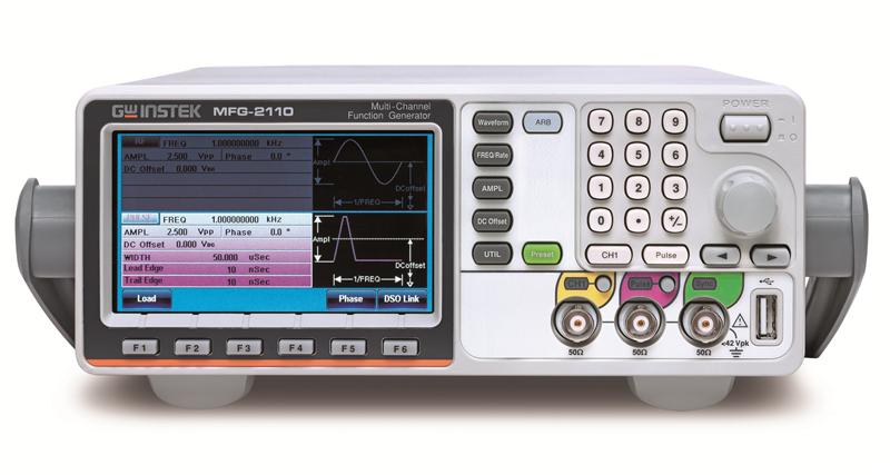

GW Instek rolls out the MFG-2000 series multi-channel function generator, which has up to 5 simultaneous output channels, including CH1 and CH2 equivalent performance dual channel arbitrary function generator with the maximum 60MHz for both channels; RF signal generator, a standard AFG, which produces the maximum 320MHz sine wave and various modulation RF signals; pulse generator, whose frequency reaches 25MHz; power amplifier, which is ideal for audio range. The above-mentioned five different functionality channels are separately or totally allocated on 10 models, which extend from the basic single-channel AFG with pulse generator models to five-channel models so as to satisfy various educational and industrial applications.
The AFG channel of the MFG-2000 series outputs sine, square, and triangle, etc. The series features true point by point output arbitrary waveform characteristics of 200 MHz sample rate, 100MHz waveform repetition rate, 14 bit resolution, and 16k point memory depth. Some models provide various modulation methods such as AM/FM/PM/FSK/PWM, Sweep, Burst, Trigger, 150MHz Frequency Counter. Synchronized dual channel models provide correlated functions, including synchronization, delay, sum, and coupling. RF signal generator, a complete AFG signal source (including ARB), features various modulations, Sweep, and digital modulations such as ASK and PSK and its sine wave frequency is up to 320MHz. A full-function pulse generator with 25 MHz is equipped to all models and its pulse width, rise edge time, fall edge time are adjustable that can be applied as trigger signals. Independent input/output power amplifier with 20W, 10dB, DC-100KHz bandwidth, and distortion less than 0.1% can be applied to the audio application.
The overall design of the MFG-2000 series is earth ground isolation among output/input terminals and instrument chassis that can only be found in high-level signal sources. The output channels can sustain maximum isolation voltage up to ±42Vpk (DC+ AC peak value) to earth ground that is ideal for floating circuit tests. Multi-unit outputs can be executed without factoring in grounding reference issue. There is no additional isolation requirement for experiments such as “full-wave rectification” and “voltage doubler” which are easy and safe. An external power supply can bring up the DC bias voltage to ±42Vpk to meet the requirements of higher DC bias voltage such as automotive and educational applications.
The AFG of the MFG-2000 series collocating with AWES (Arbitrary Waveform Editing Software) allows users to easily and quickly edit arbitrary waveforms. DWR (Direct Waveform Reconstruction) allows users to collocate with GDS series digital oscilloscopes to retrieve waveforms and upload them to arbitrary generator to achieve direct waveform reconstruction. 66 built-in waveforms allow users to edit arbitrary waveforms and to output the whole segment or divided segments.
With the multi-functionality channels, the MFG-2000 series provides different industrial sectors with special dual channel waveforms, IQ modulation signals, low-frequency vibration simulation, automotive sensors, AM/FM broadcast signals, PWM motor or fan control signals, pulse synchronized signals, pulse noise, audio circuit or devices such as speaker tests. The series is ideal for various fields, including scientific research, education, research and development, production and quality control.
Panel Introduction
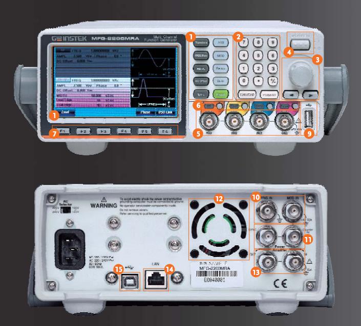
- TFT LCD Panel
- Number Panel
- Scroll Knob & Selection Key
- Power Switch
- Output Terminal
- Main Output Switch
- Function Keys
- Operation Keys
- USB Host
- Trigger & Modulation Input
- Sync and Counter Input
- Fan
- Power Amplifier Input & Output
- LAN (MFG-22XX only)
- USB Device
A. Circuit Design for Ground Isolation Among Output/Input Terminals and Instrument Chassis

Connection diagram for MFG connecting with a power supply to increase D.C. bias voltage to ±42Vpk (DC+ AC peak value).
Output channels, synchronization and modulation input/output connector grounding are isolated from instrument chassis. These connectors can sustain maximum isolation voltage up to ±42Vpk (DC+ AC peak value) to earth ground that is ideal for floating circuit tests. Multi-unit outputs can be executed without factoring in grounding reference issue. The built-in DC bias voltage of the MFG-2000 series can be applied on various waveforms. The DC bias voltage is ±5V under 50 ohm load. An external power supply can be used to bring up the DC bias voltage to ±42Vpk (DC+ AC peak value) for higher DC bias applications.
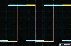
B. Pulse Generator
 |
 |
Each model of the series has a built-in pulse generator and its output frequency reaches 25 MHz. Users can set pulse width, duty cycle, rise edge time, and fall edge time to support trigger signal.
C. RF Signal Generator
| RF Channel | ASK, PSK |
| AM, FM, PM, PWm, Sweep, Burst, Trigger, Frequency Counter | |
| ARB (200MHz) | |
| Other Waveform | |
| Triangle, Ramp (1MHz) | |
| Square (25MHz) | |
| Sine wave FREQ. up to 320MHz max. |
RF signal generator is a full function AFG signal source. Identical to CH1/CH2, it can output sine, square, ramp, pulse, noise, etc. Its sine wave frequency reaches 160MHz or 320MHz. And its true point by point output arbitrary waveform function supports 200 MHz sample rate, 100MHz waveform repetition rate, 14 bit resolution, 16k point memory depth, frequency sweep and various modulation methods such as AM/FM/PM/FSK/PWM/PSK/ASK. RF signal generator can be applied as a high frequency arbitrary waveform generator, simulated signals of analog or digital broadcast stations or carrier signals of local oscillator.
D. Power Amplifier

20W/20dB power amplifier, which has a bandwidth of DC ~ 100KHz and less than 0.1% distortion. The low frequency power amplifier can be applied as an audio amplifier or a driver amplifier for piezoelectric components (collocating with an impedance transformer, 20W output) and conducts power component characteristics tests, magnetization characteristics tests(B-H curve) of magnetic materials such as ferrite and amorphous materials (collocating with an impedance transformer, 20W output)

Users can connect a speaker with the low frequency power amplifier of the MFG-2000 series to realize various physics experiments.
E. Versatile Output Waveform Selections
 |
 |
| Sine | Square |
 |
 |
| Pulse | Noise |
 |
 |
| Triangle | Ramp |
 |
 |
| DC Voltage | Arbitrary Waveform |
There are standard waveforms for the series such as sine, square, triangle, ramp, pulse, noise, DC voltage. In addition, 66 built-in waveforms allow users to easily select desired waveforms.
F. Various Modulation Function
 |
 |
| Amplitude Modulation | Frequency Modulation |
 |
 |
| Frequency-shift Keying Modulation | Amplitude-shift Keying Modulation |
 |
 |
| Phase Modulation | Pulse Width Modulation |
 |
 |
| Phase - Shift Keying Modulation | Sum Modulation |
The series supports AM, FM, PM, FSK, PWM and SUM modulation. RF channel not only has the above-mentioned modulation capabilities but also supports advanced modulations such as ASK and PSK Modulation. The most modulation sources can be internal or external. Applications include communications systems' base band, motor control and light adjustment.
G. Sweep Function
 |
 |
The series supports frequency sweep and amplitude sweep that can also integrate other functions, including linear/logarithm, one-way (saw tooth)/two-way (triangle) waveforms, continuous/ single trigger/gated trigger to meet various application requirements by different sweep methods. Frequency sweep carries out tests on the frequency response of electronic components such as filter and low frequency amplifier.
H. Burst Function
 |
 |
The series supports N-period or gated trigger. Phase angle, duration time, frequency, waveform infinite can be adjusted to meet non-continuous output applications.
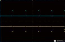
I. The Output Correlated Functions of Equivalent Performance Dual Channel
 |
 |
 |
| Differential Signal | Sine and Cosine Signal | Square Wave Phase Setting |
The CH1 and CH2 of MFG-2203M/2206M/2260MFA/2260MRA can be applied separately. These two channels provide four correlated functions, including sum, coupling, tracking and phase.
-
The coupling function allows users to freely set ratio and offset values for frequency and amplitude of both channels to realize that all parameters are simultaneously effective for both channels. The measurement of the Third-Order Intercept Point for an amplifier and the simulations of two different frequency oscillators outputting signals are two applied examples for coupling function.
-
The tracking function can produce 180 degree phase offset differential signals with same frequency and amplitude.
-
The phase function allows users to freely set phase parameters for both channels such as sine wave, cosine wave, and square wave signals.
-
The sum modulation function can sum up two signals into one and output this signal via one channel. One of the related applications is to sum up sine waveform and noise to execute speaker distortion tests.
J. Four Methods to Obtain Arbitrary Waveforms

Front Panel Operation
Via single unit's panel, arbitrary waveforms can be selected, edited, stored, recalled, output, triggered from 66 built-in waveforms.

CSV File Upload
Support CSV file upload produced by MATLAB and Excel.

Direct Waveform Reconstruction
Collocate with GDS series digital oscilloscopes to retrieve waveforms and upload them to arbitrary generator to achieve direct waveform reconstruction.

Arbitrary Waveform Editing PC Software
Use AWES to edit complex waveforms. The software supports waveform mathematical operation. The waveform series includes Uniform Noise, Gaussian Noise, Rayleigh Noise, various digital codes such as non zero code, Manchester and RS-232, etc.
K. Flexible Arbitrary Editing
Other Brand’s ARB Operation

The Operation Mode Of "user-defined Retrieval Of Segmented Output" Increases Arbitrary Efficiency!
GW Instek ARB Operation

- Maximum Five Output Channels
- 2 Equivalent Performance Arbitrary Channels Frequency : 1Hz~60MHz
- Pulse Generator Frequency : 25MHz
- Power Amplifier : Low Frequency, 100KHz, Output 20W
- RF Channel Frequency (FG/ARB/MOD) : 320MHz
- True Point by Point Output Arbitrary Waveform Function : 200MSa/s
- 100MHz Repetition Rate, 14-bit Resolution,16k Point Memory Depth
- Earth Ground Isolation Design Among I/O Terminals and Instrument Chassis
- Frequency Counter : 150MHz, 8 bits
- AM/FM/PM/ASK/FSK/PSK/SUM/PWM Modulation
- 4.3 Inch TFT Color Display
Other
| Accessories | GTL-101× 2 Quick Start Guide ×1 CD (user manual + software) ×1 Power cord×1 |
| Safety designed to | g Safety designed to EN61010-1 |
| Weight | Approx. 2.5kg |
| Dimensions (WxHxD) | 266(W) x 107(H) x 293(D) mm |
| Storage Temperature | -10~70˚C, Humidity: ≤70% |
| Pollution Degree | IEC 61010 degree 2, Indoor use |
| Operating Altitude | 2000 Meters |
| Operating Environment | Temperature to satisfy the specification : 18 ~ 28˚C Operating temperature : 0 ~ 40˚C Relative Humidity: ≤ 80%, 0 ~ 40˚C ≤ 70%, 35 ~ 40˚C Installation category: CAT II |
| Power Consumption | 30W or 80W(With power amplifier) |
| Power Source | AC100~240V, 50~60Hz or AC100~120V, AC220~240V, 50~60Hz; |
| Display | 4.3’’ TFT LCD 480 × 3 (RGB) × 272 |
| Interface | LAN, USB |
| Save/Recall | 10 Groups of Setting Memories |
Advanced Functions
| Frequency Counter |
| ||||||||||||||||
| Burst |
| ||||||||||||||||
| Trigger Delay |
| ||||||||||||||||
| External Trigger Input |
| ||||||||||||||||
| External Modulation Input |
| ||||||||||||||||
| Trigger Output |
| ||||||||||||||||
| PM |
| ||||||||||||||||
| SUM |
| ||||||||||||||||
| PWM |
| ||||||||||||||||
| FSK |
| ||||||||||||||||
| Sweep |
| ||||||||||||||||
| AM Modulation |
| ||||||||||||||||
| FM Modulation |
|
Dual Channel Function (CH1 / CH2)
| Dsolink | √ |
| Coupling | Frequency(Ratio or Difference) Amplitude & DC Offset |
| Track | CH2=CH1 |
| Phase | -180˚ ~ 180˚ Synchronize phase |
CH1 / CH2
| Pulse Characteristics |
| ||||||||||||||||
| Ramp Characteristics |
| ||||||||||||||||
| Square wave Characteristics |
| ||||||||||||||||
| Sine wave Characteristics(3) |
| ||||||||||||||||
| Sync Output |
| ||||||||||||||||
| Waveform Output |
| ||||||||||||||||
| Offset |
| ||||||||||||||||
| Output Characteristics(2) |
| ||||||||||||||||
| Frequency Characteristics |
| ||||||||||||||||
| Arbitrary Functions |
| ||||||||||||||||
(3). DC offset set to zero
(2). Add 1/10th of output amplitude and offset specification per ºC for operation outside of 0ºC to 28ºC range (1-year specification).
(1). A total of ten waveforms can be stored. (Every waveform can be composed of a maximum of 16k points.)
Pulse Generator
| Jitter | 100ppm +500ps(4) |
| Overshoot | <5% |
| Leading and Trailing Edge Time(5) | 10ns~ 20s(1ns resolution) (limited by the current frequency and pulse width settings) |
| Variable duty Cycle | 0.1%~99.9%(limited by the current frequency setting) |
| Pulse Width | 20ns~999.7ks(limited by the current frequency setting) |
| Frequency | 1µHz~25MHz |
| Offset | ±1 Vpk ac +dc (into 50Ω) 2Vpk ac +dc (Open circuit) |
| Amplitude | 1mVpp to 2.5 Vpp (into 50Ω) 2mVpp to 5 Vpp (open-circuit) |
(5).Only Pulse channel support
RF Generator
| ASK |
| ||||||||||||||
| PSK |
| ||||||||||||||
| Modulation/Sweep |
| ||||||||||||||
| Ramp Characteristics |
| ||||||||||||||
| Square Wave Characteristics |
(4). Jitter specification for RF Generator: 20ppm +5ns. | ||||||||||||||
| Sine Wave Characteristics (3) |
(3). DC offset set to zero | ||||||||||||||
| Waveform Output |
| ||||||||||||||
| Offset |
| ||||||||||||||
| Output Characteristics (2) |
(2). Add 1/10th of output amplitude and offset specification per ºC for operation outside of 0ºC to 28ºC range (1-year specification). | ||||||||||||||
| Frequency Characteristics |
| ||||||||||||||
| Arbitrary Functions |
| ||||||||||||||
Power Amplifier
| Ground Isolation | 42Vpk max |
| Total harmonic distortion | < 0.1% (Ampl>1Vpp) 20Hz~20 kHz |
| Overshoot | 5% |
| Full Power Bandwidth | DC-100KHz |
| Rise/Fall Time | <2.5uS |
| Output Current | 1.6Amax |
| Output Voltage | 12.5Vpmax |
| Output Power (RL=8Ω) | 20W (Square) |
| Gain | 20dB |
| Working Mode | Constant Voltage |
| Input Impedance | 10KΩ |
| Input voltage | 1.25Vpmax |
General
| Modulation /Sweep/Burst/ Frequency Counter | yes |
| RF Generator (Function With ARB) | no |
| Power Amplifier | yes |
| 25MHz Pulse Generator | yes |
| CH2 Function With ARB | no |
| CH1 Function With ARB | 20MHz |
Do you have a 30MHz Single channel Arbitrary Function Generator with pulse generator, modulation that needs to be calibrated?
We offer standard traceable calibration and ISO 17025 accredited calibration services.
Get your 30MHz Single channel Arbitrary Function Generator with pulse generator, modulation calibrated today! Click Here!
There are currently no reviews for this product.