Soken DAC-PG-3F - Winding Tester


The DAC-PG-3F is impulse test equipment for testing of low-voltage rotator windings. The equipment is composed of a surge impulse generator circuit, phase selector unit (selection between U, V, and W), and waveform recorder circuit to provide a different method type of impulse testing instrument.
A TFT (thin-film transistor) liquid crystal display (LCD) is integrated for waveform measurement, offering excellent viewability of waveforms. Waveforms are stored in digital format, allowing observation and comparison of waveforms even at lower frequencies of pulse generation, which contributes to the elimination of unwanted stresses on specimens.
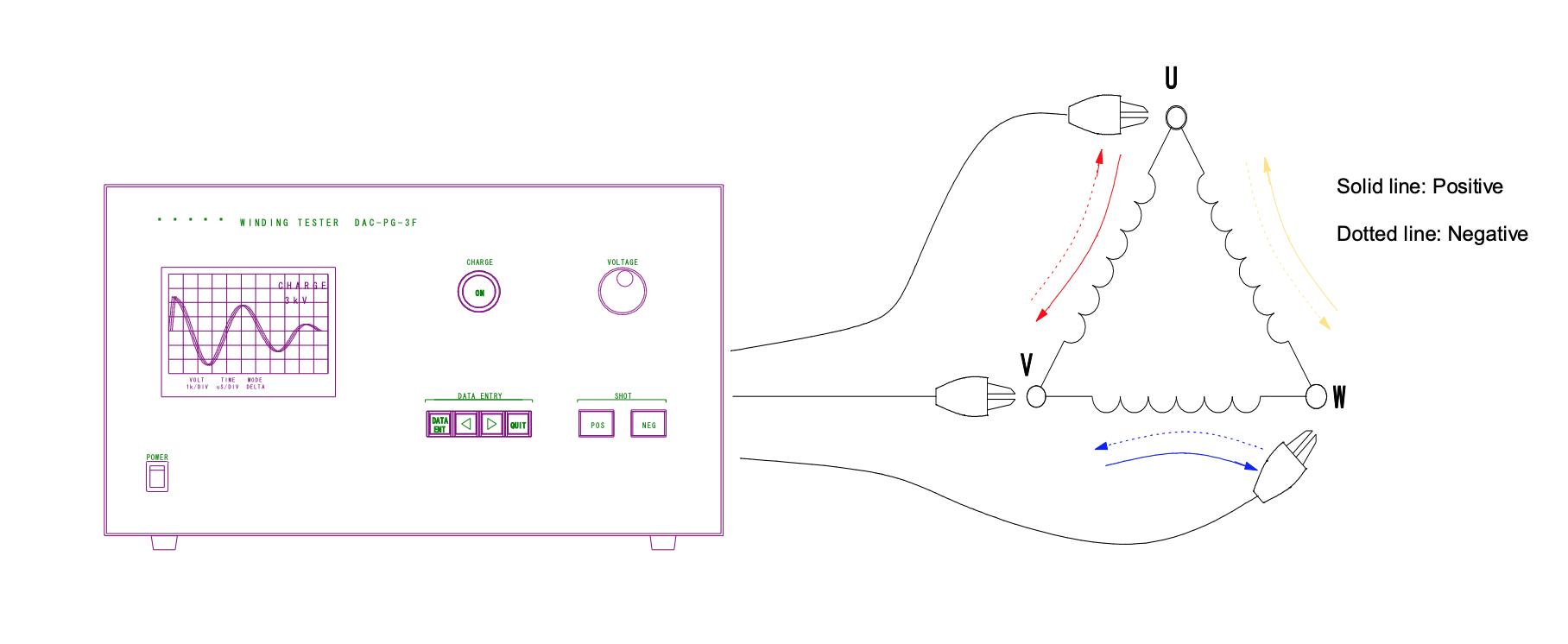
The testing phase selector unit in the equipment provides simple testing.
Functions
- Self-comparison mode:
- Waveforms are recorded through automatic selection between the phases of three-phase motors to allow a comparison of waveforms between the individual phases.
- Waveforms are superimposed using color-coding for the three phases, ensuring ease of comparison.
- Difference comparison mode:
- Individual phases are displayed based on their differences from the reference phase. This allows a comparison between waveforms with greater accuracies.
- Waveform superimposition mode:
- Waveforms are displayed superimposed for a certain time. This helps identify variations in waveforms.
Operation Procedure
- Holding down the CHARGE button, increase the CHARGE voltage to a specified value.
- Press either SHOT button, POS or NEG, to produce positive or negative pulses.
- High-precision and reproducible observations due to the integrated digital waveform capturing circuitry
- Not susceptible to the effects of magnetic fields due to the integrated LCD
- Compact and lightweight due to the semiconductor switches
- Simple design, leading to ease of operation suited for field observation
- Compatible with medium capacitance specimens with the use of higher impulse energy
General
| Output Voltage | 1 to 5 kV (Load resistance 1 kΩ) |
| Duration of pulse wave front | Approx. 1 uS (Load resistance 1 kΩ) |
| Duration of pulse wave tail | Approx. 40 uS (Load resistance 1 kΩ) * Output voltage refers to a maximum voltage at a resistance load of 1 kΩ. Duration of pulse wave tail refers to a duration of wave tail at a load resistance of 1 kΩ. Under inductive loads, wave shape changes (causing vibration), leading to changing maximum output voltages. |
| Output Channels | 3 |
| Pulse Repetition Rate | Approx. 3 times/sec. |
| Output Selection | Automatic selection between (U-V, V-W, W-U) and (V-U, W-U, U-W) |
| Impulse energy | 1.65 J |
| Maximum current | 250 A |
| Display unit | TFT LCD screen |
| Limiting time-axis resolution | 40 nS |
| Maximum capturing time | 300 µS |
| Waveform Resolution | 12 bit |
| Maximum storage point | 500Pt. |
| Interface | USB |
| Power input | 100V 50/60 Hz |
| Dimensions & Weight | W424 x H250 x D450 (mm), Approx. 15 kg |
Do you have a Winding Tester that needs to be calibrated?
We offer standard traceable calibration and ISO 17025 accredited calibration services.
Get your Winding Tester calibrated today! Click Here!
There are currently no reviews for this product.